background image

Page 71 


NOTE:


192.168.0.1 & 192.168.0.255 cannot be used by any device in the network. 


192.168.0.1 


192.168.0.255 


IP address range of C5-IPC 


S1  

POWER 

AG             ON                                 DIP 


PA       VR600  

1      2      3      4      5      6  

L INK 

IN-USE 


192.168.0.2 ---- 192.168.0.239 


1   2   3  

SW1  


P+  P-  P+  P-    RS4 85     JWB(IN)  JWB(OUT) CN(MDS)  ETHERNET 


C5-IPC 


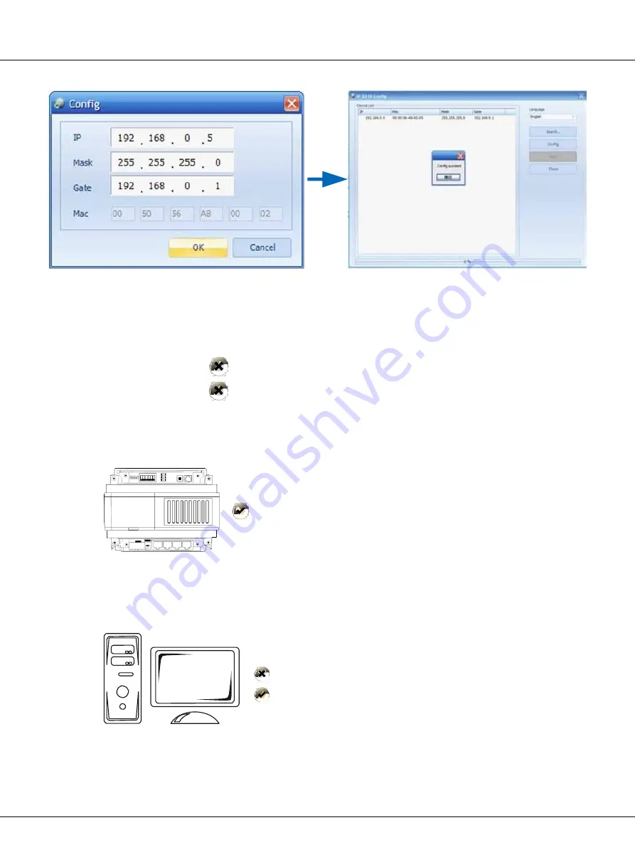
PC  IP  address 


IP8210Config 


192.168.0.2 


192.168.0.3  ---- 192.168.0.254 


Because default IP address of C5-IPC is 192.168.0.2, 

it’ll make a conflict if PC is set to 192.168.0.2, then PC can- 

not search the C5-IPC. That

’s why PC should not be set to 192.168.0.2. 

Содержание CAT-5 wired

Страница 1: ...CAT 5 video intercom system Technical guide...

Страница 2: ...Page 2 SYSTEM FEAGUTES Large capacity Simple installation Signal isolution Debugonline PRODUCT FEAGUTES MenuGuide Intercom PictureMemory Multi Channels...

Страница 3: ...DPC 518ID 17 2 3 1 1 Features 17 2 3 1 2 Parts and Functions 17 2 3 1 3 Terminal Description 18 2 3 1 4 Door Station Functions 19 2 3 1 5 Specifications 19 2 3 2 Indoor Monitor DPM 573TMD 20 2 3 2 1...

Страница 4: ...ss Controller GP ACS 31 2 3 4 8 Network Camera IP Converter CM IPC 32 2 3 4 9 System Power Supply PS5 33 2 3 4 10 CAT5 System Cables 34 Chapter 3 CAT5 SYSTEM CONFIGURATION 35 3 1 One Entrance without...

Страница 5: ...program settings 43 4 1 2 4 Debug Tools 47 4 1 3 Configuration DPC 518ID 49 4 1 3 1 How to enter debug mode 49 4 1 3 2 Program Menu overview 49 4 1 3 3 Basic program settings 50 4 1 3 4 Debug Tools 5...

Страница 6: ...meters Settings 75 4 4 2 5 Controller Concept 75 4 4 2 6 Examples 76 4 5 C5 MDS Setting 81 4 5 1 Port Description 81 4 5 2 Settings 81 4 5 2 1 Level Switch setting 81 4 5 2 2 Address Setting 81 4 5 2...

Страница 7: ...2 2 1 Set PC IP address 96 5 2 2 2 Connect device to PC directly or network 98 5 2 2 3 IP8210 Config Software 98 5 2 3 IP Address Setup by IP Device Software 101 5 2 3 1 Set PC Station IP 101 5 2 3 2...

Страница 8: ...meters setting 124 5 3 8 3 Advanced 124 5 3 9 Tip Device 125 5 4 IP Agent 2012 126 5 4 1 Introduction 126 5 4 2 Login 126 5 4 3 Operate Interface 127 5 4 4 Monitor Viewer 128 5 4 4 1 Name Function in...

Страница 9: ...urity Startup 143 5 5 IP Access 2012 144 5 5 1 Introduction 144 5 5 2 Login 144 5 5 3 Access Device Console 146 5 5 3 1 Cards information Device 146 5 5 3 2 Card Information Database 146 5 5 3 3 Utili...

Страница 10: ......

Страница 11: ...Page 7 Chapter 1 CAT5 System Overview 1 1 System Description 11 1 2 System Features 12 1 3 System Applications 13...

Страница 12: ...5 system is designed to perform not only common functions like making call conversation monitoring door lock release network alarm and message to indoor monitor but also other advanced functions like...

Страница 13: ...hout the need for any masonry work to save the cost Long distance of signal transmission The system automatically equalizes and amplifies the au dio and video signal restoring high quality performance...

Страница 14: ...without having to meet them at the door If family is away missing a visitor is no longer an issue using this system with automatic recording capability In this system conversation can be set up betwe...

Страница 15: ...lications Chapter 2 CAT5 System Parts 2 1 Wiring Diagram 15 2 2 Product List 16 2 3 System Parts 17 2 3 1 Outdoor Station DPC 518ID 17 2 3 2 Indoor Monitor DPM 573TMD 20 2 3 3 Switchboard DPG IP G21 2...

Страница 16: ...Distributor Indoor Monitor SOS PS5 C5 IPC IP Converter Switchboard DPG IP G21 C5 M DS PS5 Multi DoorStation Switch PS5 PS5 RF CARD RF CARD Exit Button 1 2 3 4 5 6 7 8 9 0 Unit Door Station 1 2 3 4 5...

Страница 17: ...ce Mount 125 225 23 24V 40mA 24V 260mA ACCESSO RIES C5 F422 DIN Rail 140 150 60 24V 60mA 24V 120mA C5 F414 DIN Rail 140 150 60 24V 60mA 24V 120mA C5 F4 DIN Rail 88 140 32 24V 8mA 24V 80mA C5 IPC DIN R...

Страница 18: ...ion Access control ID IC card function The visitors can call indoor monitor and Switchboard The keyboard is designed with automatic backlight CCD super brightness LED light compensation Door lock rele...

Страница 19: ...Description 12V 12VDC power output LK GND Power ground LK COM Common contact of the Relay NO Normally open contact of the Relay Can be set to be normally closed EB Exit button connection port Short E...

Страница 20: ...isitor call resident block No must be input at first Switchboard can call monitor this door station while Indoor moni tor cannot Open the locks by password or ID IC card As per the prompt on the displ...

Страница 21: ...800 pieces color pictures memory optional 8 areas alarm for house security which can warn Switchboard Secondary door station connection 2 slave monitors can be set with 1 master monitor No additional...

Страница 22: ...ang up the monitor unit 9 Connection port Includes bus port outdoor station port alarm zone and 485 signal port 10 SD card slot Use to insert SD card for SD card model only 2 3 2 3 Terminal Descriptio...

Страница 23: ...in standby press the directly call Switchboard to call the Switchboard and wait for it to answer the call Press end button to end the conversation The device will go back to standby status Call other...

Страница 24: ...itor Additionally DPG IP G21 has other functions such as alarm receiver depends on system configuration Max 8 DPG IP G21 can be connected in system 10 inch digital TFT with its resolution of 800x480 p...

Страница 25: ...r flash when in talking state 5 Unlock Button Press to release the door for visitors during talking or monitoring 6 Call Button Press to activate the intercom function page 7 Handset Pick up to talk w...

Страница 26: ...e BUS audio and video signals and then distributes them to the connected indoor monitors There are three types of distributors C5 F4 C5 F414 and C5 F422 2 3 4 1 C5 F4 C5 F4 is a normal distributor It...

Страница 27: ...system from shutting when one or some of the monitors gets faulty to guarantee each monitor in the system work independently Parts and Functions P P PA S1 IN USE LINK RS485 P P Power input DC 24V PA T...

Страница 28: ...DC 24V PA Test button S1 DIP Switch Power Power indicator Always ON IN USE Status Indicator ON while working LINK Signal indicator Flicker means signal is transmitted in bus ERROR Error indication ON...

Страница 29: ...AN and RS485 connection port Parts and Functions PA Reset Press and hold PA for 3 seconds to initialize C5 IPC If initialization com JT AG S1 P O WER P A V R600 S1 POWE R plete successfully power off...

Страница 30: ...rt RJ45 Network Interface Standard Ethernet interface Working temperature 100 C 400 C Dimension 140 150 60 mm 2 3 4 5 Multi Door station Switcher C5 MDS C5 MDS is used when there are more than one doo...

Страница 31: ...RS 485 PC port Used to update the firmware of C5 MDS Specification Power input DC 24V Standby Current 50mA Working Current 80mA Connection Port RJ45 Working temperature 100 C 400 C Dimension 140 150...

Страница 32: ...king current 135mA Working temperature 100 C 400 C Connection port RJ45 Dimensions 140 150 60mm JWP101 RS485 C N NET FM SET 2 3 4 7 Independent Access Controller GP ACS GP ACS is an independent access...

Страница 33: ...OUT RS485 CN RD1 CN RD2 Card reader connec tion port connected to independent card reader JWP LINK JWB IN USE P A C N NET CN LK1 CN LK2 Lock connection port connected to lock and outlet button CN DSI...

Страница 34: ...l output RJ45 port connected to LAN Specification Power supply DC24V Standby current 78mA Working current 135mA Working temperature 100 C 400 C Connection port RJ45 Dimensions 140 150 60mm JWP JWV JW...

Страница 35: ...5A Working temperature 200 C 600 C Dimensions 97 159 37mm 2 3 4 10 CAT5 SystemCables Type Cable Specification Usage Remark Bus RVV2 1 0mm Power cable for distributor FromDoorstationtoIPconverter IP co...

Страница 36: ...etwork 36 3 1 1 Layout 36 3 1 2 List of Accessories 36 3 2 Multi Entrances without Network 37 3 2 1 Layout 37 3 2 2 List of Accessories 37 3 3 One Entrance with Network 38 3 3 1 Layout 38 3 3 2 List o...

Страница 37: ...only one entrance without network so it can be connected without C5 IPC 3 1 1 Layout C5 F4 C5 F4 1 1 2 2 3 3 4 4 Floor N C5 F4 C5 F4 1 1 2 2 3 3 4 4 Floor N PS5 RF CARD 1 2 3 4 5 6 RVV 2 1 0 7 8 9 0 E...

Страница 38: ...1 1 2 2 3 3 4 4 Floor 1 C 5 IP C PS5 C 5 MDS C5 IPC C 5 MDS RV V 2 1 0 C AT5Cable C5 MDS C5 MDS PS5 PS5 RF CARD RF CARD 1 2 3 4 5 6 7 8 9 0 1 2 3 4 5 6 7 8 9 0 Exit Button Exit Button 3 2 2 List of A...

Страница 39: ...414 C5 F414 1 1 2 2 3 3 4 4 Floor 1 C5 IPC PS5 C5 I P C T o LA N WAN RVV 2 1 0 RF CARD 1 2 3 CAT5 Cable 4 5 6 7 8 9 Exit Button 0 3 3 2 List of Accessories Model Description DS Outdoor station call mo...

Страница 40: ...2 2 3 3 4 4 Floor N C 5 F22 C5 F422 1 1 2 2 3 3 4 4 Floor 1 C 5 IP C PS5 C5 IPC T o LAN WAN RVV 2 1 0 C5 MDS C5 MDS C A T 5 C able PS5 PS5 RF CARD RF CARD 1 2 3 4 5 6 7 8 9 0 1 2 3 4 5 6 7 8 9 0 Exit...

Страница 41: ...onnection Diagram 59 4 3 Monitor Setting 60 4 3 1 Concept of Address 60 4 3 2 Address setting on Monitor 61 4 3 3 Address Setting with door station 68 4 4 C5 IPC Setting 70 4 4 1 Port Description 70 4...

Страница 42: ...e installer and debug tool can be activated under this mode Working Mode Function Normal mode Daily use for tenants calling talking unlocking Debug mode Special mode for installer quick access to alls...

Страница 43: ...n 1 7 Parameters 1 8 Installer Code 1 9 Default Set 2 Setup 2 1 Language 2 2 Tone Select 2 3 Tone Volume 2 4 Unlock code 2 5 CodeCheck 2 6 Clock 2 7 Setup Code 2 8 About 1 I n s t a l le r S e t u p 2...

Страница 44: ...mory To choose to use the memory of door station or that of C5 IPC when access cards areinuse 0 Store and read cards from the memory of Door station 1 Store andread cards from C5 IPC 0 Use memory of D...

Страница 45: ...tors 90 8 CallRing Times How many times the door station ring when it makes a call 0 9 Use to call Whethertoinput tocall afterentering the room number 0 Table 2 Item Descriptions Factory Set 1 LocalIM...

Страница 46: ...ith ST NSW or C5 IPC 0 Use with C5 IPC Setup Debug State 2 Setup Item Descriptions Factory Set 1 Language When Severallanguages are available can beset to choose different languages 1 English 2 Tone S...

Страница 47: ...d s 3 P r es s t o p r o g ra m B a c k V id e o E n tr y S y st e m V id e o E n tr y S y st e m V id e o E n tr y S y st e m When in Debug Mode press 3 Monitor Program is launched Program the monito...

Страница 48: ...a v e n t r y S y st e m V id e o E nt r y Sy st e m 4 1 2 4 Debug Tools Entering debug tools Note Each Debug Option can be activated or de activated separately Each Debug Command is a sub menu to ex...

Страница 49: ...eostat Variable Resistor serves as adjuster to adapt to distance 2 Auto Dialback The Auto Dial Back option is designed to simplify field debugging and to realize single person testing Also it is alway...

Страница 50: ...us and Tools Debug State Menu Item Submenu D e b u g S t a t e 0 R e d i a l 1 T o o l s 2 E x i t s Tools 1 In s t a l l e r S e t up 2 S e t u p 3 C a r d M e m or y 4 O n l i n e M on it or s 5 O n...

Страница 51: ...cess cards areinuse 0 Use memory of DS for access 1 UseC5 IPCforaccess 0 Use memory of DS for ac cess 5 Doorplate Mode 1 To choose the input mode when you call monitor It can be set to from 1 to 8 dig...

Страница 52: ...6 Talk Timing Maximum talk time available in a call 90 Table 2 Item Descriptions Factory Set 1 Ring Numbers To set the monitor coded 0099 as local Switchboard so when the user does Call Switchboard on...

Страница 53: ...2 Setup Item Descriptions Factory Set 1 Language To choose different languages via SD Card 01 English 2 ToneSelect 12 calling tones are available 03 3 Tone Volume Adjust thevolumeof calling tone 03 4...

Страница 54: ...P to select Back 7 S et u p C o d e 8 A b o u t 9 D e f a u l t Back Sav e Press key Input 8002 then input Setup Code or Admin Code 88888888 or 66666666 by default Press 4 to enter unlock code item In...

Страница 55: ...t About accessMemory The access cards can be saved in the door station for this the Card memory in Installer setup Must be set to 0 It is 0 by default The access cards also can be saved in the C5 IPC...

Страница 56: ...the display 2 D e l e t e B y C a r d Show T he C ard Back Save 2 D e l e t e B y C a r d C ar d numbs 1 5 9 7 7 1 3 1 Show The Card Back Sav e Delete cards by associated Room Code Enter Delete by M C...

Страница 57: ...ck Sav e Press 9008 then Installer code to enter the Debug mode then 1 to enter Tools page Debug Tools menu is shown Press 1 4 to select different tools Enter the starting number and ending starting a...

Страница 58: ...2 Auto Dialback The Auto Dial Back option is designed to simplify field debugging and to realize single person testing Also it is always used to get a Monitor s Room Code After Auto Dial Back is acti...

Страница 59: ...e starting number and ending starting and to start search the moni tors on line 5 Online Devices This tool is used to identify whether C5 MDS C5 IPC and C5 IMC are connected When it is star tup the co...

Страница 60: ...the door station directly or from the additional power supply we call these two internal power supply and external power supply separately 4 2 2 1 Door Lock Controlled withInternal Power To C5 IPC or...

Страница 61: ...tput Power on to unlock ty pe Unlock Output 0 by def ault Power of f to unlock ty pe Unlock Output 1 4 3 Monitor Setting 4 3 1 Concept of Address Address codes are the numbers letters used by resident...

Страница 62: ...e Switchboard or common door station are outside call When making this call 7 dig its address is required XXX ABCD XXX represents the IP address of C5 IPC of the building ABCD represents the address o...

Страница 63: ...9 2 Touch the User Setup icon to enter setup interface password will be required Input 2412 to get access to the setup 3 Now touch the User Code and input the new user code to be the address of the mo...

Страница 64: ...Page 60 Chapter 4 CAT5 System Settings DPM 535 C5 1 In Standby Mode Press the menu button on the surface of the front panel 2 When it shows the calendar press the menu button again...

Страница 65: ...e Setup and press menu button to enter setup page Door Station Tone 01 Door Bell Tone 05 GuardUnit Tone 05 No Disturb Mode off Installation Exit 4 Go to Installation and input password 2412 then press...

Страница 66: ...4 CAT5 System Settings 5 Go to Room Address Alarm In Out Delay 40 Date And Time Set Room Address Other Settings Information Exit 6 Enter the new Room address via navigation button and press Menu to sa...

Страница 67: ...monitor 1 In standby mode press the Menu button 03 29 2012 Thu 11 44 AM 2 In the Calendar page press the menu again to enter main menu Main Menu Monitor Intercom Alarm Function User Setup Close Exit...

Страница 68: ...r Setup page just like the following picture shows Input 0080 then press Menu button to confirm then entry room code setting status Code Number 000 0010 delete remotes 0011 add remote 0020 set as door...

Страница 69: ...set 0031 in delay set 0080 room id set 0090 test armed 0093 direct call gl vd on 0094 direct call gl vd oV 8008 MM DD YYYY 8009 DD MM YYYY 8012 12 hour format 8013 24 hour format 2412 restore to defa...

Страница 70: ...ain page Press Direct Call Guard Unit icon DPM 535 C5 2 TALK M ENU M ONITOR Intercom Function Call Guard Unit Direct Call Guard Unit Intercom Call Exit Press Call button to entry Intercom Function pag...

Страница 71: ...succeeds Then back to normal status you can repeat the similar operation to program next monitor 4 4 C5 IPC Setting C5 IPC is a controlling and network enabling unit Wherever network is required there...

Страница 72: ...cted OFF NoC5 MDS connected DIP2 Audio Channel ON Apply C5 F414 OFF Apply C5 F4 or C5 F422 DIP3 Video Channel ON Apply C5 F422 OFF Apply C5 F4 or C5 F414 DIP4 Door station mode selection ON Door stati...

Страница 73: ...address ofC5 IPC is 192 168 0 2 Setting steps as follows 1 Connect C5 IPC and PC and set IPaddress of PC to 192 168 0 X Assume that PC IP is 192 168 0 105 S1 POWER AG ON DIP PA V R 6 0 0 IP 192 168 0...

Страница 74: ...k Search to start searching the connected C5 IPC 4 Config IP address Select the Device in the Device List Frame 5 Click on Config to config IP Assume it s set to 192 168 0 5 don t change Mask Gate inf...

Страница 75: ...0 1 2 3 4 5 6 LINK IN USE 192 168 0 2 192 168 0 239 1 2 3 SW1 P P P P RS 48 5 JWB IN JWB OUT CN MDS E TH ERNE T C5 IPC PC IP address IP8210Config 192 168 0 2 192 168 0 3 192 168 0 254 Because default...

Страница 76: ...P r o g r a m To o l s 5 O n l i n e M on i t o r E X I T 9 0 0 9 1 D S S e r i a l N O 2 U n l oc k T i m i n g 4 C ar d M e m o r y 5 D oo r pl a t e M o d e 7 P ar a m e t e r s 8 I n s t al l er C...

Страница 77: ...To other monitors PS5 AC C5 F4 C5 F4 1 2 3 4 1R 2W GD VD T R T R Z1 Z2 Z3 Z4 COMCOMPR 3Y 4B FV FV P AU P P P D1 D2 To other monitors To Next C5 F4 F4 F4DV F4Q ON DIP Keep 3 jumpers LAN Note that VD S...

Страница 78: ...P P P P VD SET HI VD 1 2 3 4 C5 F422 To other monitors 1R 2W GD VD T R T R Z1 Z2 Z3 Z4 COM COM PR 3Y 4B FV FV P AU P P P D1 D2 PORT A PORT B PORT C PORT D JWB IN JWB OUT VD SET L HIGH P P P P PA S1 1...

Страница 79: ...F4DV F4Q Keep 3 jumpers LAN CAT5 RVV2 1 0mm Note that ID Code 8001 1 setting must be set to 1 PORT A PORT B PORT C PORT D JWB IN JWB OUT VD SET L HIGH P P P P PA S1 1 ON 2 T R ERROR INUSE LINK POWER...

Страница 80: ...1 setting must be set to 1 JWB IN JWB IN4 JWB IN3 JWB OUT P JWB IN2 JWB IN1 1V 4A 2V 2A 1V 1A CN MDS 1 2 3 4 C5 F414 To other monitors PS5 AC 1R 2W GD VD T R T R Z1 Z2 Z3 Z4 COM COM PR 3Y 4B FV FV P...

Страница 81: ...T R 1 2 3 P P P P RS485 SW1 JWB IN JWB OUT CN MDS ETHERNET PA VR600 S1 POWER LINK IN USE AG 1 ON ON DIP DIP 2 3 4 5 6 1 2 3 P P P P RS485 SW1 JWB OUT CN MDS ETHERNET C5 IPC IP MR18 AC F4 F4DV F4Q Kee...

Страница 82: ...ase refer to 2 3 4 5 Multi Door station Switcher C5 MDS for more details 4 5 2 Settings 4 5 2 1 Level Switchsetting The C5 MDS will always be used together with C5 IPC the level switch must be set to...

Страница 83: ...4 inputs from the door station for C5 MDS with different address Input number is unique and different see below table Address Input Description Input number First C5 MDS JWB IN1 1 JWB IN2 2 JWB IN3 3...

Страница 84: ...e 8001 1 setting must be set to 1 JWB IN ON DIP JWB OUT P 1V 4A 2V 2A 1V 1A 1V 4A 2V 2A 1V 1A CN MDS 1 2 3 4 C5 F414 To other monitors To other door To other door PS5 AC 1R 2W GD VD T R T R Z1 Z2 Z3 Z...

Страница 85: ...distributor can come from Door station or C5 IPC Distributor to Door Station 4 6 Accessory Parts C5 F4 C5 F4 1 2 3 4 1R 2W GD VD T R T R Z1 Z2 Z3 Z4 COMCOMPR 3Y 4B FV FV P AU P P P D1 D2 PS5 1 2 3 6...

Страница 86: ...ORT D JWB IN JWB OUT VD SET L HIGH P P P P PA S1 1 ON 2 T R ERROR INUSE LINK POWER T R PORT A PORT B PORT C PORT D JWB IN JWB OUT P P P P VD SET HI VD 1 2 3 4 C5 F422 To other monitors 1R 2W GD VD T R...

Страница 87: ...Each distributor was equipped with video match switch and it has two states HIGH and VD SET In one block only one of the distributors is set to VD SET the rest all to be set to HIGH The distributor th...

Страница 88: ...GD VD T R T R Z1 Z2 Z3 Z4 COM COM PR 3Y 4B FV FV P AU P P P D1 D2 To Next C5 F414 CAT5 RVV2 1 0mm Note that ID Code 8001 1 settingmust be set to 0 F414 PORT A PORT B PORT C PORT D JWB IN JWB OUT VD SE...

Страница 89: ...be set to 1 PORT A PORT B PORT C PORT D JWB IN JWB OUT VD SET L HIGH P P P P PA S1 1 ON 2 T R ERROR INUSE LINK POWER T R PORT A PORT B PORT C PORT D JWB OUT JWB IN JWB OUT P P P P P A1 D1 D2 P P P P P...

Страница 90: ...ifferent cameras by itself the video also can be set to show different cameras by turn Multi camera Maximum 4 cameras can be connected to the CM IPC by applying VT QSW PS5 AC CAT5 RVV2 1 0mm Coaxial C...

Страница 91: ...3 IP Device 2012 104 5 3 1 Introduction 104 5 3 2 Login 104 5 3 3 Project Property 106 5 3 4 IP Node Config 107 5 3 5 Block Config 110 5 3 6 Default project parameters 113 5 3 7 Management of Block C...

Страница 92: ...m Softwares 5 4 7 Setting 139 5 5 IP Access 2012 144 5 5 1 Introduction 144 5 5 2 Login 144 5 5 3 Access Device Console 146 5 5 4 Card Console 150 5 5 5 Pass Rule 153 5 5 6 Report 154 5 5 7 Report Car...

Страница 93: ...Page 89 5 1 PC Station Installation 1 Double Click Setup exe Start to install PC Station 2 Select language and then click next...

Страница 94: ...Page 90 Chapter 5 CAT5 System Softwares 3 Click Next 4 Select folder for installation then click next...

Страница 95: ...Page 91 5 Click Install button to begin the installation then waiting till installation finishes 6 Then click Finish button to confirm it...

Страница 96: ...2 Chapter 5 CAT5 System Softwares 7 Please note the default login info ID Device Password 123456 Server Name Machine Name K2012 Database Name K2012 Customers need to enter the Server name and Database...

Страница 97: ...an one device have the same IP address only one of them can be available by IP8210 config or IP Device 4 If PC the device to be set to have the same IP the device can t be detected by IP8210 Config or...

Страница 98: ...Local Network Status window 4 Select Internet Protocol TCP IP item in the Networking tab of Local Network Properties win dow 5 Select Use the following IP address option in the General tab of Inter Pr...

Страница 99: ...5 5 2 2 2 Connect device toPC directly or network The following is a diagram of direct connection PS5 24V 2 Wire C5 IPC Ethernet CAT5 IP8210 Config exe PC 5 2 2 3 IP8210ConfigSoftware Run the IP8210 c...

Страница 100: ...ares 1 Press Search button to search the device You can press Stop button to end the search after the device has been detected Just like the following picture shows 2 Select the device in the Device L...

Страница 101: ...ng Modify IP address but remember to leave the Mask and Gate as it is and then press OK button to confirm Its Mac address will be automati cally modified simultaneously 4 If setup is successful it wil...

Страница 102: ...2 3 1 Set PC Station IP Assume using the following IP address IPaddress 192 168 0 246 Subnet mask 255 255 255 0 Default gateway 192 168 0 1 Note IP address range of PC station must be from 192 168 X...

Страница 103: ...Page 99 5 2 3 3 Set IP Address 1 Start IP Device software 2 Right click on CAT5 System then select IP Node Config in the pop up menu 3 In IP Node Config page press Scan Check button...

Страница 104: ...how devices that are detected Assume that 192 168 0 80 is the device that is supposed to be set to 192 168 0 82 5 Double click 192 168 0 80 then a window pops up for modifying IP input 82 then Mac add...

Страница 105: ...P Device is used to construct a new project and save project information to a database for IP Agent whose information is based on the database It can set the parameters of C5 IPC on line 5 3 2 Login S...

Страница 106: ...hapter 5 CAT5 System Softwares Check the information then Click Login to access IP Device File Include Change and Password and Exit Language Include English and Chinese Simplified Help Include Content...

Страница 107: ...Page 103 5 3 3 Project Property Right click on Default Project then it will pop up a menu Select Project Property It will pop up a window for setting project property...

Страница 108: ...input some info about project Insert time line Insert the created time in CAT5 System frame When finish the basic setting click on Save to save the project information 5 3 4 IP Node Config Now when t...

Страница 109: ...P G21 Guard Unit PC PC Station IP Agent For example in CAT5 System see the table IP Nodes can be configured like the following picture IP Device 192 168 0 81 82 84 86 Door Station A Block B Block C Bl...

Страница 110: ...ct Click on Save to exit Also if all the decivices are installed in the system we can click on Scan Check to search the devices on line and then added them to the project See below Now go back to the...

Страница 111: ...sn t opened indicates the model of IP Node is wrong selected or wrong DIP switch setting of C5 IPC Note that the Refresh Onlinechecks only the IP Node such as C5 IPC PC station and DPG IP G21 5 3 5 Bl...

Страница 112: ...0024 and 0031 0034 Door station Configuration DS Config Right click on A Block Select DS Config on the pop up window Config just like the fol lowing picture Click Save button to confirm Then the soft...

Страница 113: ...nables you to add monitors in batches When all the monitors are added Click close to save and exit Now go back to the block interface and right click on A Block Select Check IM Online on the pop up wi...

Страница 114: ...l check if the monitors are online automatically Note that only 2 extended monitors are valid in the system Refer to latter chapters about how to activate the extended monitors We can configure other...

Страница 115: ...ck C5 IPC and swithc boards IP address list 5 3 6 1 Guard center priority The calls from the blocks can be transferred to maximum 8 guard centers in turn When the first guard center is off line or bus...

Страница 116: ...will be sent to all the switch boards in the list After the setting click Save button to finish setup and Write to all device to set all the C5 IPC con nected 5 3 6 3 Input table Input table is to ma...

Страница 117: ...ame instead of the IP address Note When the table is finished do Write to all device to complete the parameters setting Here please note that 1 Switch can call any of the devices directly by their nam...

Страница 118: ...changed and saved according to different requirements on each of the C5 IPC Right click on the C5 IPC and select the Management see the below window Read From Device To upload all the parameters saved...

Страница 119: ...r View Edit To make and edit the call table View on device to view the call table of the device 2 IP CallTable See IP Call Table in the previous chapter 3 Call Priority The call priority here unlike t...

Страница 120: ...indow below Button Description Read from Device Read all the parameters stored in the device Write To Device Write all the parameters to the device Reset To Default Reset all the parameters in the dat...

Страница 121: ...ivert function when no answer Extend Room TableMode To set the code rule for multi monitors in one apartment Network Intercom Enable or Disable Network Intercom between monitors 2 Call Priority Set pr...

Страница 122: ...time 4 MDS MDS serves as multi door station switcher When there are more than one door station in one block it must be used to make the system work properly The system now allows maximum 2 C5 MDS to...

Страница 123: ...served don t change the set ting easily Special function IMC Set Enable Dis able for IMC F4XX driver Set the Distributor type G Ca ll Typ e W hen the switchboard calls monitor to set it as a network c...

Страница 124: ...itch setting it just can be changed on C5 IPC For more details refer to C5 IPC settings in part 4 5 3 8 Management of Common C5 IPC The Common C5 IPC is set to work with Common door station and common...

Страница 125: ...l Talk Time To set limitation for talking time Ranging from 10 to 600s IM Ring Number To set the ring times for monitor when called Ranging from 1 to 4 Call Transfer Wait Time To set waiting time befo...

Страница 126: ...mak ing the IP call table Rows of Room Call Table To set the limitation of rows when making the Local call table 5 3 9 Tip Device Tip Device is debug tool to find the physical C5 IPC By activatintg th...

Страница 127: ...talking with entrances or monitoring Capture picture of entrances when monitoring or calling entrances Record video automatically when answering incoming call Record video manually when monitoring or...

Страница 128: ...is strongly recommened that the password should be changed via IP Admin Otherwise it may cause information leak and the responsibility is on the user 5 4 3 Operate Interface Input the correct User ID...

Страница 129: ...nitor Viewer 4 Record Launches the Record Viewer 5 Capture Launches the Capture Viewer 6 Setup Open the setup page 7 Exit Terminates the application 5 4 4 Monitor Viewer From the right upper corner of...

Страница 130: ...dow 7 Record Performs Stop Recording the selected video window 8 Digital Keypad Open digital keypad for operation 9 Exit Exitmonitoring 10 Maximum Maximize the monitoring screen 11 Aspect Ratio Select...

Страница 131: ...DS CDS or an in coming calling from DS CDS 8 1 2 3 4 5 6 7 Item Description 1 Capture Capture a picture of the video window 2 Record Performs Stop recording the video window 3 Unlock 1 Unlock the latc...

Страница 132: ...e 2 Device Offline 3 PC Online but IP Agent is not running 4 Invalid Model 5 Call 6 Monitor GL PC GL PC is a list of Switchboards including Guard Station and IP Agent In the GL PC frame you can see ot...

Страница 133: ...s Hand up button to end the conversation DS CDS All the door stations common door stations are listed in this frame You can input full or part of a device name to search one DS or CDS in the Search in...

Страница 134: ...up button to end the conversation Press button to monitor the related DS or CDS The video will be shown in the focused moni tor window Monitor All the monitors of one selected building are listed in t...

Страница 135: ...nter talking status else press Refuse to deny the calling 2 Talking established if the called Switch board picks up 2 Talking established after accept the calling you can press Hand up button to end t...

Страница 136: ...All Call All call info including outgoing calls incoming call missed calls 2 Calls Outgoing call info 3 Incomings Incoming call info 4 Missed calls Missed call info Double click one record to call th...

Страница 137: ...Item Description 1 Device Name Displays the recorded device name 2 RecordTime Displays the time when the video audio was recorded 5 4 5 3 Record List Record operation will be activated in the followi...

Страница 138: ...no video 3 Video Record Video record for DS CDS when monitoring based on setting no audio 4 Talk Record Talk record for conversation with video 5 Record Filter Filter record ased on specific time and...

Страница 139: ...and address Video Screen Displays captured pictures Slide bar Slide to adjust the number of pictures that can be viewed simultaneously in the video screen Scroll bar Slide to browse other pictures TO...

Страница 140: ...BROWSE MODE BIG PICTURE MODE If you want to back to BROWSE MODE just double click on one picture in the video screen 5 4 7 Setting From the right upper corner of the IP Agent main screen click the but...

Страница 141: ...tchboard Capture Capture Path Select a path to save all captured pictures Record Record Path Select a path to save all record documents Auto Recording On Call Activate auto recording when IP Agent ans...

Страница 142: ...l Monitor calls guard unit in emergency Defense out of home Signal will be sent to Switchboard when customers activate defense func tion Undefense Signal will be sent to Switchboard when customers dea...

Страница 143: ...nnel selection in the main frame Monitor On Start To select specific DS CDS to monitor automatically when IP Agent starts View Device list display setting Show IP Deselect the option to hide IP addres...

Страница 144: ...one for handset Ring Volume Adjust Ring Volume for handset 5 4 7 5 Security Startup Password Control For Setting Select the Enable item input the password and confirm it If you want to change the sett...

Страница 145: ...cess controller gets card information Via Door Station and RFID link USB 5 5 2 Login 1 Start the IP Access 2012 Software On your desktop click icon that has been created automatically IP Access gets s...

Страница 146: ...the users are responsible for any information leak The following are two examples of login failure you will see the error messages if input wrong information Input incorrect ID or Password Input inco...

Страница 147: ...le to open the door Unregister Cards Cards added via door station directly but PC doesn t have these cards info Click Process button to add these cards info to database in PC New Event The number of n...

Страница 148: ...ccess time related room number and whether pass granted or not 5 5 3 3 Utilities Import cards from file to device Click Import Cards to import a backup file suffixed by CDF to the related device Expor...

Страница 149: ...eir related device respectively Refresh all Refresh all devices to check if it s online Close Exits current window 5 5 3 4 Configure Click on Configure It will pop up a window of the Device Management...

Страница 150: ...Search Search all the devices to check if it s online 9 Set Clock All Synchronize time of all devices by PC time 10 Set PassRuleAll Set Pass Rule for all devices 11 Check onlineall Check all devices...

Страница 151: ...ick Detail tab just like the right picture shows Authorized Entrance All the C5 IPC that are authorized to be associated with the slected card No Authorized Entrances All the C5 IPC that have nothing...

Страница 152: ...saved it will be automatically download ed to the device If the card is control card one at least one pass rule must be cho sen There are totally 6 pass rules available After adding new cards new car...

Страница 153: ...target info must be identical to Filter Value exactly target info is not equal to Filter Value target info is less than Filter Value target info is greater than Filter Value target info is less than o...

Страница 154: ...of a residential area The control card takes effect only during the time set via the pass rule and any time else it can not open the door Click Pass Rule into setting interface just like the following...

Страница 155: ...vices Click Print button to print report click on Export to export a report document 5 5 7 Report Card Click Report Card Enter Report Card interface Click Query to show all the CARDS just like the fo...

Страница 156: ...Page 152 Chapter 5 CAT5 System Softwares Click Print to print report card click Export to export a report document...

Отзывы: