17
Figure 2-2
The 8-ch rear panel is shown as below. See Figure 2-3.
Figure 2-3
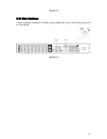
The 16-ch real panel is shown as below. See Figure 2-4.
Figure 2-4
Please refer to the following sheet for detail information.
1
Video input
2
Audio input
3
Video CVBS output
4
Audio output
5
Network port
6
USB port
7
HDMI port
8
RS232 port
9
Video VGA output
10
Alarm input/alarm output/RS485 port
11
Power input port
12
Power button
When connect the Ethernet port, please use straight cable to connect the PC and use the
crossover cable to connect to the switcher or router.
2.3
Connection Sample
Please refer to
X281H281H281H285H
Figure 2-5
X
for connection sample.
Содержание 1U J Series
Страница 1: ...1U J Series Standalone DVR User s Manual 1...
Страница 44: ...44 Figure 4 23 Figure 4 24 Figure 4 25...
Страница 78: ...78 Figure 6 11...


