X|Smart™ Users Manual
Page 8
X Stream Designs, Inc.
1.2 Applications
The X|Smart_PSP power supply system and web based user interface was designed to meet numerous industry applications. It
gives the user much more functionality than just an interface to trigger wiping and cleaning of the enclosure dome. With the
integrated relays and power sensors, users can remotely control multiple accesory power ports and monitor power usage in real-
time. A great tool for remote camera systems and especially o
ff
-grid powered systems.
The X|Smart_PSP system is integrated into our X|Clear and X|Rain enlosure systems and is also available as an option in our X|Mod,
X|Cold and X|Heat enclosure systems. The next generation X|Smart_PSP will include an integrated UPS with battery backup power
and integrated solar charge controller systems.
Example Applications Include Coastal Monitoring Cameras, Rainy Environments, O
ff
-Grid Powered Camera Locations, Remote
Camera Applications and any installation that requires housing additional camera accesorry components.
1.3 Accessory Power Connections & Indicators
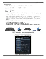
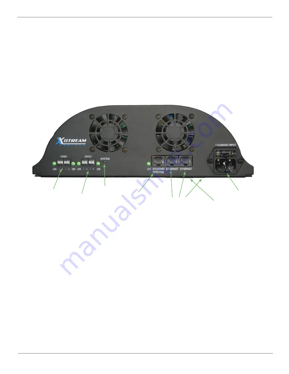
[2] 12VDC Accessory Power Ports
The X|Smart system has two 12VDC accessory power ports. Each port is individually controlled (on/o
ff
) via the X|Smart web inter-
face. Next to each accessory port is a green indicator LED which illuminates when power is available on the port.
[2] 24VDC Accessory Power Ports
The X|Smart system has two 24VDC accessory power ports. Each port is individually controlled (on/o
ff
) via the X|Smart web inter-
face. Next to each accesory port is a green indicator LED which illuminates when power is available on the port.
[1] 48VDC Accessory Power Over Ethernet Network Port
The X|Smart system has one 48VDC accessory POE network port which is controlled (on/o
ff
) via the X|Smart web interface. Next
to the POE port is a green indicator LED which illuminates when 48VDC power is available on the port.
[3] 10/100Mbps RJ45 Network Switch Ports
The X|Smart system has 3 non POE powered 10/100Mbps Network switch ports. Two are accesible on the face of the X|Smart
chassis while the third is underneath as indicated in Figure 1.4 above.
115/230VAC & 24VAC Power Inputs
The X|Smart power supply chassis takes either 115/230VAC or 24VAC input power. The 115/230VAC power input is located on the
face of the X|Smart power supply chassis as shown in Figure 1.4 above. The 24VAC power input is located underneath the power
supply chassis.
System LED
The System LED is a blue LED light which blinks every 5 seconds indicating the system is live and operating normally. Allow ap-
proximately 10-15 seconds at power up for the System LED to start blinking.
[2] 12VDC Ports
[2] 24VDC Ports
System LED
[1] 48VDC POE Port
115/230VAC Input
[3] 10/100Mbps
RJ45
Figure 1.4 - X|Smart_PSP Connections & Indicators
24VAC Input
Содержание XSmart PSP
Страница 1: ...X Smart PSP Users Manual Revision 1 2...


