background image

29

GEARING

GEAR MESH Adj.

CLUTCH SPRINGS

CLUTCH SHOE

911410

SHF M4x10

908308

SCH M3x8

908312

SCH M3x12

359050

BB 5x10x4

961025

S 2.5

962050

S 5x10x1

964073  

S 7x10x0.2 

964074  

S 7x10x0.3

964075  

S 7x10x0.5

Please note that the engine is not parallel with the chassis centerline, so 

that the clutchbell engages the spur gear at a slight angle. This is correct 

and will not have any effect on handling, performance, or lifespan of 

any parts.

2~2.5°

DETAIL

ANGLED ENGINE POSITION

CORRECT

7x10x0.2 / 0.3 / 0.5

3x8

5x10

2.5

Adjust engine 

position to 

achieve proper 

gear mesh

Use appropriate shims to achieve proper 

clutchbell endplay

11~11.2 

mm

FUEL TANK & ENGINE

It is very important that your XB9 has properly-adjusted 

gear mesh. Adjust the gear mesh so there is adequate (or 

slightly larger) space between the spur gear and clutchbell 

teeth. Adjust the gear mesh by sliding the engine mounts in 

the slots of the chassis. You should be able to rock one gear 

back and forth slightly while holding the other one firmly. 

Be sure to check the gear mesh all the way around the spur 

gear. Tighten the screws once the engine alignment and 

gear mesh are correct, and then re-check the gear mesh to 

ensure the engine mounts did not move.

DETAIL

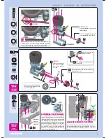
Tighten the clutch nut using 

HUDY tool #107581

Hold the flywheel using HUDY Flywheel 

Tool #182015

Use the cone included with your engine, 

or use optional XRAY cone #358540

NOTE ORIENTATION

IMPORTANT!

Failure to use these shims 

may  cause  the  flywheel 

pins  to  come  out  after 

some time.

When installing the engine, first check that the drive shaft does not 

touch the engine. If it does, remove some material from the engine 

mount as shown to make some room between engine and shaft.

IMPORTANT

EXTREMELY IMPORTANT

These bearings must still be regularly serviced and 

replaced when worn out.

Note the orientation of the clutch shoes. 

The short side of spring must be in the 

groove of the flywheel nut.

Содержание XB9

Страница 1: ......

Страница 2: ...ith paints and or cement if used not included in kit Immediately after using your model do NOT touch equipment on the model such as the motor and speed controller because they generate high temperatur...

Страница 3: ...e right to make the final determination of the warranty status of any component or part Limitations of Liability XRAY makes no other warranties expressed or implied XRAY shall not be liable for any lo...

Страница 4: ...lug Igniter Starter Box Battery Pack Steering and Throttle Servos Battery Charger Receiver Lexan Paint Fuel Special Tool for all turnbuckles nuts HUDY 108090 CA Glue Phillips 5 0mm HUDY TOOLS Socket 5...

Страница 5: ...r part DRIVE SHAFT PINS SERVICING TIP To enjoy the longest possible lifespan of the drive shafts and diff outdrives it is extremely important to properly service the drive shaft pins Inspect the pins...

Страница 6: ...N 2x11 6 10 BAGS 940816 903312 355040 964060 355030 971060 355020 940816 355090 964030 980212 971060 355080 355063 355063 Use HUDY Ball Bearing Grease for servicing 106220 Standard 106221 Extra 106222...

Страница 7: ...of the diff oil is 42 1g Donotoverfillthedifferential If there is too much oil in the differential it may leak after it cools down after use To enure you have the same amount of oil from rebuild to re...

Страница 8: ...35 5080 DIFF PIN 2 35 5090 DIFF GASKET 4 90 3312 HEX SCREW SFH M3x12 10 94 0816 HIGH SPEED BALL BEARING 8x16x5 BLUE COVERED 2 96 4030 WASHER S 3 5x12x0 2 10 96 4060 WASHER S 6x18x0 2 10 97 1060 SILIC...

Страница 9: ...he weight approximately 40g 40g 2 1g 42 1g 2 Slowly pour oil into the diff and watch the weight Add 2 1g of oil into the diff The approximate weight of the diff oil is 42 1g To enure you have the same...

Страница 10: ...ED 4MM 35 5110 BEVEL DRIVE GEAR 12T 35 5236 XB9 CVD DRIVE SHAFT COUPLING HUDY SPRING STEEL 35 5416 XB9 CENTRAL CVD SHAFT UNIVERSAL JOINT HUDY SPRING STEEL 35 5425 XB9 FRONT CENTRAL CVD DRIVE SHAFT HUD...

Страница 11: ...10 BEVEL DRIVE GEAR 12T 35 5236 XB9 CVD DRIVE SHAFT COUPLING HUDY SPRING STEEL 35 5416 XB9 CENTRAL CVD SHAFT UNIVERSAL JOINT HUDY SPRING STEEL 35 5625 XB9 REAR CENTRAL CVD DRIVE SHAFT HUDY SPRING STEE...

Страница 12: ...M SHIMS 35 3484 REAR ANTI ROLL BAR 2 4MM 35 7212 LOWER INNER PIVOT PIN F R 2 90 1303 HEX SCREW SB M3x3 10 90 1305 HEX SCREW SB M3x5 10 90 1312 HEX SCREW SB M3x12 10 90 1408 HEX SCREW SB M4x8 10 90 231...

Страница 13: ...th on car handling please refer to HUDY Off Road Set up Book 209099 The tables describe the amounts of rear anti squat rear toe in rear track width change depending on the combinations of eccentric bu...

Страница 14: ...318 SH M3x18 3x5 3x8 903308 SFH M3x8 L R 2x 1 5mm 6mm Follow the TECH TIP on page 5 to install the pivot balls 3x3 L R Step check for free movement 0mm STEP DETAIL 3x18 DETAIL DETAIL DETAIL INITIAL PO...

Страница 15: ...g and is recommended for flat technical tracks Shims for wheelbase adjustment L R L R Graphite Grease HUDY 106210 2mm Check for free movement To tighten the setscrew you can also use the HUDY 17mm Whe...

Страница 16: ...wn Special Tool for all turnbuckles nuts HUDY 108090 INITIAL POSITIONS INITIAL POSITIONS NOTE ORIENTATION NOTE ORIENTATION Right thread Left thread Right thread Left thread 39 mm INITIAL POSITIONS RIG...

Страница 17: ...FRONT ANTI ROLL BAR 2 4MM 35 3371 SET OF COMPOSITE LOWER ARM SHIMS 35 7212 LOWER INNER PIVOT PIN F R 2 90 1303 HEX SCREW SB M3x3 10 90 1305 HEX SCREW SB M3x5 10 90 1312 HEX SCREW SB M3x12 10 90 1408...

Страница 18: ...20 21 22 23 24 14 22 23 24 25 26 Total caster is the angle that the C hub is to the flat chassis bottom Casterisaffectednotonlybyfrontkick upbutalso by the C hub caster The combination of both repres...

Страница 19: ...12 SB M3x12 902318 SH M3x18 903308 SFH M3x8 L R 2x 1 5mm 6mm Follow the TECH TIP on page 5 to install the pivot balls Step check for free movement DETAIL DETAIL Loosen the 3x5 setscrew if the anti rol...

Страница 20: ...EW SH M4x14 10 90 2418 HEX SCREW SH M4x18 10 94 0814 HIGH SPEED BALL BEARING 8x14x4 BLUE COVERED 2 94 1319 HIGH SPEED BALL BEARING 13x19x4 BLUE COVERED 2 96 0030 NUT M3 10 98 0263 PIN 2 5x13 10 98 031...

Страница 21: ...ools to tighten as shown NOTE ORIENTATION Adjustment block towards outside 3x18 3x25 NOTE ORIENTATION Left thread Right thread Left thread Right thread Adjustment block towards outside Follow the TECH...

Страница 22: ...OATED SWISS 7075 T6 3MM 35 1200 FRONT REAR BUMPER V2 35 3088 COMPOSITE REAR BRACE V2 90 2316 HEX SCREW SH M3x16 10 90 3312 HEX SCREW SFH M3x12 10 90 3412 HEX SCREW SFH M4x12 10 96 0030 NUT M3 10 BAG 9...

Страница 23: ...23 903312 SFH M3x12 902316 SH M3x16 903412 SFH M4x12 960030 N M3 FRONT REAR ASSEMBLY SH 3x16 SFH 3x12 DETAIL...

Страница 24: ...JOINT 6 8MM 2 90 2308 HEX SCREW SH M3x8 10 90 2310 HEX SCREW SH M3x10 10 90 3308 HEX SCREW SFH M3x8 10 90 3310 HEX SCREW SFH M3x10 10 90 3312 HEX SCREW SFH M3x12 10 90 3314 HEX SCREW SFH M3x14 10 90 3...

Страница 25: ...balls RIGHT THREAD LEFT THREAD 32 8 mm 32 8 mm 4x10 SFH 3x12 SFH 3x10 SFH 3x14 SH 3x10 SH 3x10 SH 3x8 SH 3x8 2mm alu shim 1mm alu shim 3x20 3x20 NOTE ORIENTATION Adjustment block towards outside Left...

Страница 26: ...M3x30 10 90 3308 HEX SCREW SFH M3x8 10 90 3412 HEX SCREW SFH M4x12 10 Fibre pads together Temporarily insert brake disk between pads to set correct gap 0 5 mm 354121 355012 CENTER DIFF 354110 354130 3...

Страница 27: ...903308 SFH M3x8 CENTER DIFF BRAKE Before inserting 3x30 long screws loosen the four flat head screws in the upper plate by 1 2 turn Tighten all screws after assembly 3mm 0mm DETAIL NOTE ORIENTATION O...

Страница 28: ...358513 358531 961025 358561 962050 359050 351153 903410 358722 903310 903314 903314 960030 901405 960030 903310 903310 911410 908308 351153 CLUTCHBELLS 358512 12T OPTION 358513 13T STANDARD 358514 14...

Страница 29: ...idingtheenginemountsin the slots of the chassis You should be able to rock one gear back and forth slightly while holding the other one firmly Be sure to check the gear mesh all the way around the spu...

Страница 30: ...s the fuel tank volume by 2cc and is recommended for use when the fuel filter is used The smaller insert decreases the fuel tank volume by 1cc 1CC fuel tank insert 2cC fuel tank insert The fuel tank h...

Страница 31: ...NUT M3 10 Left thread Right thread Use appropriate servo arm K KO Propo JR Sanwa Multiplex H Hitec F Futaba Receiver battery not included Servo Grommet not included 306310 356003 356003 902310 902312...

Страница 32: ...eight Front 60g 351180 Plug the connectors into the receiver in Step 2 NOTE ORIENTATION Optional switch 356050 When receiver switch is used use hobby knife to CAREFULLY remove the material from the co...

Страница 33: ...s shims use them as shown Use the same procedure when building both front and rear shocks REAR shocks long 2x 358041 358262 352460 358162 358042 358042 358083 960026 358040 358223 358123 970100 971034...

Страница 34: ...2x 1 2mm PISTON SHORT SHOCK BODY SHORT SHOCK ROD 2x 1 3mm PISTON LONG SHOCK BODY LONG SHOCK ROD EXTREMELY IMPORTANT Do not push the shock rod straight through the lower shock body assembly O ring dama...

Страница 35: ...ock rebound setting is 0 as described on page 34 Alternatively you may set the shock rebound setting to 50 or 100 as described below Remove the shock springs before performing shock rebound adjustment...

Страница 36: ...ARBURST YELLOW 4 OPTION 90 1303 HEX SCREW SB M3x3 10 90 2308 HEX SCREW SH M3x8 10 90 2310 HEX SCREW SH M3x10 10 90 2318 HEX SCREW SH M3x18 10 90 2319 HEX SCREW SH M3x18 LEFT THREAD 10 90 3312 HEX SCRE...

Страница 37: ...SILICONE TUBING 10mm Brake rod Tighten screw until snug Pivots should move freely CUTAWAY VIEW Servo screw not included 3x25 L R INITIAL POSITIONS INITIAL POSITIONS On the rear left arm use the silver...

Страница 38: ...eep the fuel tubes together use tubing holders To tighten the setscrew you can also use the HUDY 17mm Wheel Nut Tool 107570 NOTE ORIENTATION Apply air filter oil and follow the engine instructions to...

Страница 39: ...urn collar to thread brake rod INTO pivot To loosen brakes turn collar to thread brake rod OUT of pivot Engine idling 0 5mm ADJUST INDIVIDUAL LINKAGES SEPARATELY TO AVOID INTERFERING WITH THE OPERATIO...

Страница 40: ...t used Screw used Screw not used XB9 offers revolutionary flex setting possibilities Depending on the traction surface track layout you can change the flex setting as you need XB9 has 3 main Multi Fle...

Страница 41: ...mmended that the shocks be re filled and bled before a large event If building or pairing new shocks always make sure they are the same length using a shock length measuring tool and adjust the lower...

Страница 42: ...t primed Bad glowplug or dead glowdriver battery Fuel lines fuel filter air cleaner or muffler is clogged Engine is flooded due to over priming Carburetor is not adjusted properly Throttle servo linka...

Страница 43: ...BLUE BLUE VIOLET PURPLE ANTI ROLL BAR OTHER OTHERS OIL cST REBOUND PISTONS 1 3mm 1 4mm 1 2mm HOLES HOLES 10 8 6 HOLES HOLES HOLES 10 8 6 VER 1 0 XRAY REAR FRONT SOFT DIRT ASTRO TURF ROLL CENTER 0 5 1...

Страница 44: ...ebook com teamxray www twitter com teamxray www youtube com xrayracing You Tube RC AMERICA 2970 BLYSTONE LANE SUITE 109 DALLAS 75220 TEXAS USA PHONE 214 744 2400 FAX 214 744 2401 xray rcamerica com 5...

Отзывы: