x0xio Installation
Product Name
x0xio
Instruction ver
1.06
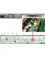
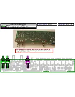
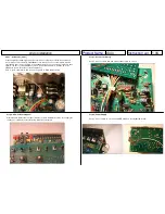
Step 11 -
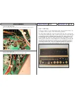
Accent Sweep
Cut a 4“ piece of green wire and connect pad P to R72:
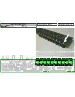
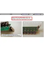
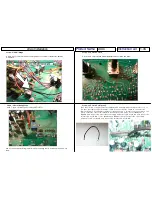
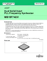
Step 12 -
VCO Out & VCF In
If you are installing the I/O kit only pad O is not used.
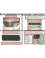
Use a scrapped resistor lead as a jumper and connect pads Q and R on the new PCB.
Cut a 5” piece of yellow wire and connect pad S to C17(-) on the x0xb0x mainboard. Cut a
5” piece of red wire and connect pad T to C17(+) on the x0xb0x mainboard:
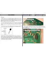
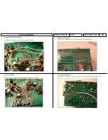
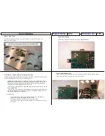
Step 13 -
Filter CV In
Cut a 4” piece of white wire and connect pin U to R47 on the x0xb0x I/O board:
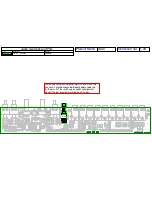
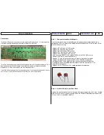
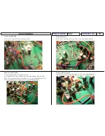
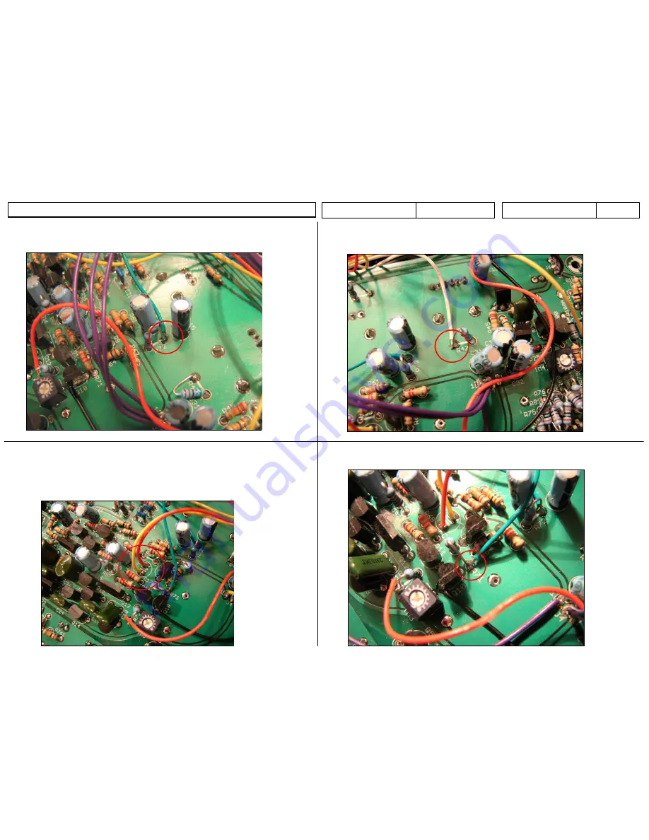
Step 13 -
Filter CV In(Cont)
Cut a 5” piece of green wire and connect pad V to R71 on the x0xb0x mainboard:

