x0xio Installation
Product Name
x0xio
Instruction ver
1.06
Conventions:
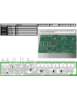
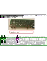
- Pinheads: When the instructions are referring to pad A, pad B etc… it’s referring to the
silkscreen lettering designating each solder pad on the new PCB:
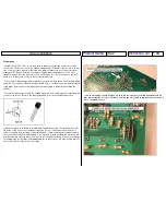
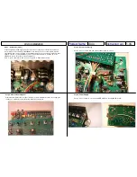
- All of the connections are made to the component side of the x0xb0x mainboard. This is
done because the full x0xi0 kit adds a new pcb that resides just above the x0xb0x
mainboard. It’s also easier to work from the component side.
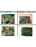
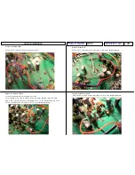
If you follow the steps and refer to the pictures you will not need the schematic in front of
you as you go, just read the steps and copy what you see in the pictures..
Step 1 -
Changes to standard x0xb0x parts
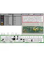
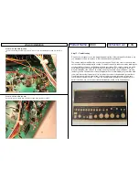
If you’re working with an existing x0xb0x you will need to remove and/or replace these
components. There is a bag in the kit labeled
x0xb0x Mainboard Parts
that contains all the
parts installed in this step.
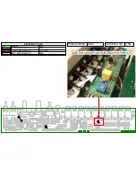
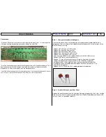
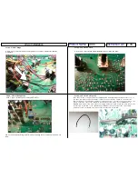
- Replace R47 with the 3.3k 1/4W resistor.
- Replace R61 with the 0 Ohm resistor.
- Replace R62 with the 68k 1/4W resistor.
- Replace R121 with the 150k 1/4W resistor.
- Replace R122 with the 68k 1/4W resistor.
- If you are using a BA6110 VCA replace R155 with the 100k 1/4W resistor.
- Remove R186 (only if installing Accent Out).
- Remove C17 (you will not have to re-use this part, a new one is included).
- Compare component C43 on your x0xb0x to the 1000uF/6.3v capacitor
included in the kit. If the height of the part currently installed is greater than
the height of the new included part then replace it with the new part (this is to
allow for PCB clearance).
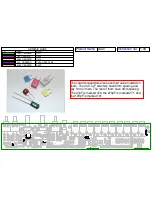
- Replace C20 & C21 with the 0.1uF red dipped polyester capacitors:
Step 2 -
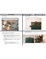
x0xb0x I/O Board to new Rear Panel
Replace the stock rear panel with the new part. Don’t apply the overlay at this time, it will be
done later after the kit has been installed. Attach the x0xb0x I/O board but not the new PCB
just yet – there’s a connection to do first:

