background image

Disassembly

2 - 14 Removing the System Memory (RAM) - 2

2.Disassembly

Removing the System Memory (RAM) - 2

Memory Upgrade Process

1.

Turn off the computer, and turn it over and remove the battery (

page 2 - 5

) and remove the keyboard (

page 2 - 5

).

2.

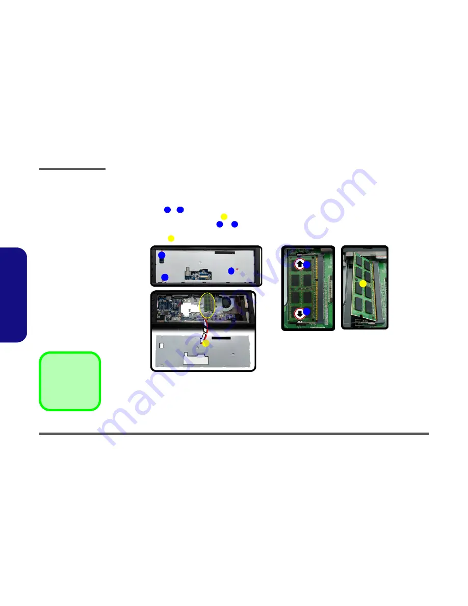
Remove screws 

 - 

 from the keyboard shielding plate.

3.

Remove the keyboard shielding plate 

.

4.

Gently pull the two

 release latches 

 & 

 on the sides of the memory socket in the direction indicated by 

the arrows (

Figure c

).

5.

The RAM module 

 will pop-up, and you can then remove it.

6.

Insert a new module holding it at about a 30° angle and fit the connectors firmly into the memory slot.

7.

The module’s pin alignment will allow it to only fit one way. Make sure the module is seated as far into the socket 
as it will go. DO NOT FORCE the module; it should fit without much pressure.

8.

Press the module in and down towards the mainboard until the slot levers click into place to secure the module.

9.

Replace the shielding plate, keyboard, LED cover module and screws (make sure to reconnect the keyboard 
cable) -see 

Figure 9 on page 2 - 13

.

10. Restart the computer to allow the BIOS to register the new memory configuration as it starts up.

Figure 10

 RAM-2 Module 

Removal (cont’d.)

a. Remove screws. and

keyboard plate.

b. Remove the keyboard

plate.

c Pull the release

latch(es) and remove
the module.

4. Keyboard Shield-

ing Plate

7. RAM Module(s)

3  Screws

1

3

4

5

6

7

a.

11

b.

2

1

3

5

6

c.

4

7

Содержание P801

Страница 1: ......

Страница 2: ...down properly and don t forget to save your work Remember to periodically save your data as data may be lost if the battery is depleted Do not expose the computer to any shock or vibration Do not plac...

Страница 3: ...its purpose If you do not have access to a compatible outlet have a qualified electrician install one When you want to unplug the power cord be sure to disconnect it by the plug head not by its wire M...

Страница 4: ...r hands or metal objects Battery Guidelines The following can also apply to any backup batteries you may have If you do not use the battery for an extended period then remove the battery from the comp...

Страница 5: ...ory Option Fingerprint Reader Module Keyboard Full size WinKey keyboard with numeric keypad Communication Built In Giga Base TX Ethernet LAN 2 0M Pixel USB PC Camera Module Factory Option Bluetooth 2...

Страница 6: ...ut Five Speakers One Sub Woofer Built In Microphone THX TruStudio Pro Environmental Spec Temperature Operating 5 C 35 C Non Operating 20 C 60 C Relative Humidity Operating 20 80 Non Operating 10 90 Po...

Страница 7: ...Locator Top View with LCD Panel Open Figure 1 Top View 1 Optional Built In PC Camera 2 LCD 3 Speakers 4 LED Status Indicators 5 Touch Sensor Instant Keys 6 8 Gaming Keys 7 Keyboard 8 TouchPad and Butt...

Страница 8: ...ight side Views Figure 2 Front Views 1 Speakers 2 LED Power Indicators Figure 3 Right Side Views 1 ExpressCard 54 34 Slot 2 Headphone In Jack 3 Microphone In Jack 4 Line In Jack 5 S PDIF Out Jack 6 Co...

Страница 9: ...ft Side Rear View Figure 4 Left Side View 1 DVI Out Port 2 Powered USB 2 0 Port 3 USB 2 0 Ports 4 RJ 45 LAN Jack 5 HDMI Out Port 6 Multi in 1 Card Reader 7 USB 3 0 Ports 8 Mini IEEE 1394 Port 9 Option...

Страница 10: ...Locator Bottom View Figure 6 Bottom View 1 Sub Woofer 2 Fan Outlet Intake 3 Component Bay Cover 4 Battery 5 HDD Bay Overheating To prevent your com puter from overheating make sure nothing blocks the...

Страница 11: ...ing the connection make sure the connector is oriented in the same way The pin1 side is usually not indicated Pressure sockets for multi wire connectors To release this connector type grasp it at its...

Страница 12: ...Do not pull on the wire 6 Peripherals Turn off and detach any peripherals 7 Beware of static discharge ICs such as the CPU and main support chips are vulnerable to static electricity Before handling a...

Страница 13: ...Slide the latch in the direction of the arrow 3 Slide the latch in the direction of the arrow and hold it in place 4 Lift the battery up Figure b and out of the battery bay 3 Battery 3 Screws 1 2 4 Fi...

Страница 14: ...the cover c Remove the screw d Push the optical device out of the computer 1 2 4 5 6 4 Hard Disk Bay Cover 6 Optical Device 4 Screws a c b 4 Blu Ray Device Bezel Removal Note that some Blu Ray module...

Страница 15: ...system s installation instructions and install all necessary driv ers and utilities as outlined in Chapter 4 of the User s Manual when setting up a new hard disk Hard Disk Upgrade Process 1 Turn off...

Страница 16: ...e hard disk board connector from the case 8 Separate the hard disk s from the case 9 Reverse the process to install a new hard disk s Figure 4 HDD Assembly Removal cont d c Remove the screws d Lift th...

Страница 17: ...t the hard disk assembly out of the compartment 6 Remove the screws to release the hard disk from the case 7 Remove the cable 8 Reverse the process to install any new hard disk s 9 Hard Disk Assembly...

Страница 18: ...f the LED cover module unsnap up the LED cover module from point on the right 4 Lift up the LED cover module and disconnect the cable 5 Remove screws from the keyboard Figure 6 Keyboard Removal a Remo...

Страница 19: ...e the module to the right as illustrated and snap down to secure it in place 12 Replace the screws on the bottom of the computer 11 12 13 e 11 12 13 f Keyboard Tabs Re Inserting the Keyboard When re i...

Страница 20: ...Removing the Primary System Memory 2 memory sockets 1 Turn off the computer and turn it over and remove the battery page 2 5 2 Locate the component bay cover and remove screws 3 Carefully a fan and ca...

Страница 21: ...it will go DO NOT FORCE the module it should fit without much pressure 11 Press the module in and down towards the mainboard until the slot levers click into place to secure the module 12 Replace the...

Страница 22: ...mory slot 7 The module s pin alignment will allow it to only fit one way Make sure the module is seated as far into the socket as it will go DO NOT FORCE the module it should fit without much pressure...

Страница 23: ...10 2 The Wireless LAN Module will be visible at point 3 Remove the screw and carefully disconnect cables 4 The Wireless LAN Module Figure c will pop up and you can remove it Figure 16 Wireless LAN Mod...

Отзывы: