5
IT
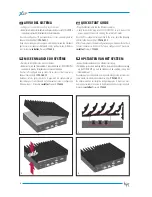
Installazione dissipatore di calore
Allineare al lato destro del dissipatore il bordo destro dell’ETI/SER XIP
(Figura 1).
Nota.
a - Il bordo posteriore del dissipatore deve essere allineato con il bordo
superiore dell’ETI/SER XIP.
b - La scanalatura presente nella parte inferiore del dissipatore dovrebbe
trovarsi al di sopra dei LED (Figura 2).
Portare il bordo sinistro del dissipatore a contatto con il bordo sinistro dell’
ETI/SER XIP (Figura 3).
Premere forte il dissipatore contro l’ETI/SER XIP; un “click” sta ad indicare
che il dissipatore è installato correttamente.
Nota.
Un piccolo spazio tra dissipatore e ETI/SER XIP è normale e non influenza
l’efficacia di funzionamento del dissipatore.
EN
Installation heat-sink
Align the right side of the heat-sink to the right edge of the ETI/SER XIP
computer (Figure 1).
Note.
a - The rear edge of the heat-sink should be aligned with the rear edge of
the ETI/SER XIP computer.
b - The indention in the bottom of the heat-sink should be above the
LEDs (Figure 2).
Allow the left edge of the heat-sink to touch the left edge of the ETI/SER
XIP computer (Figure 3).
Firmly press the heat-sink against the cover. A loud click sound indicates
that the heat-sink snapped onto the ETI/SER XIP computer. The heat-sink
is now successfully installed.
Note.
A partial gap may be observed between the heat-sink and ETI/SER XIP
computer. This is normal and does not affect the effectiveness of the
heat-sink.
FR
Installation du dissipateur de chaleur
Aligner sur le côté droit du dissipateur le bord droit de l’ETI/SER XIP
(Figure 1).
Remarque.
a - Le bord arrière du dissipateur doit être aligné avec le bord supérieur
de l’ETI/SER XIP.
b - La rainure de la partie inférieure du dissipateur devrait se trouver au-
dessus des LEDS (Figura 2).
Amener le bord gauche du dissipateur contre le bord gauche de l’ETI/
SER XIP (Figure 3).
Pousser fort le dissipateur contre l’ETI/SER XIP ; un “clic” indique que le
dissipateur est installé correctement.
Remarque.
Un petit espace entre dissipateur et ETI/SER XIP est normal et n’influence
pas l’efficacité de fonctionnement du dissipateur.
NL
Installatie van de warmte-afleider
Breng de rechterkant van de warmte-afleider op dezelfde hoogte als de
rechterrand van de ETI/SER XIP (Fig. 1).
Opmerking.
a - De rand aan de achterkant van de warmte-afleider moet zich op
dezelfde hoogte bevinden als de bovenste rand van de ETI/SER XIP.
b - De gleuf op de onderkant van de warmte-afleider moet zich boven de
LED’s bevinden (Fig. 2).
Breng de linkerkant van de warmte-afleider op dezelfde hoogte als de
linkerrand van de ETI/SER XIP (Fig. 3).
Druk de warmte-afleider stevig tegen de ETI/SER XIP. Wanneer u een “klik”
hoort, dan is de warmte-afleider correct geïnstalleerd.
Opmerking.
Het is normaal dat er zich een kleine opening bevindt tussen de warmte-
afleider en de ETI/SER XIP. Dit beïnvloedt de werking van de warmte-
afleider op geen enkele manier.

