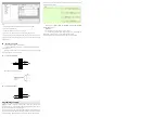
Steps:
1. open the XDPpro software, find the left project bar, click PLC config/ED.
2. choose the correct module type.
3. set the module parameters such as current input range.
4. click write to PLC, then re-power on the PLC to make the setting effective.
Note: first-order low-pass filtering weighted this sampled value with last filter output value,
and got the effective filtering value. The filter coefficient is set by user, the range is 0-254,
0 means no filter.
External connection
Please pay attention to below items when wiring:
①
please use shield cable to avoid interference, and single point connect to ground
for the shield layer.
②
when XD-2AD2PT-A-ED connects external
+
24V power supply, please choose the
power supply from PLC to avoid interference.
Current single-ended input
XD-2AD2PT-A-ED current input wiring:
PT100 temperature input
Programming example
Example:
it needs to
collect one channel pressure sensor signal (pressure sensor
performance parameter: pressure range 0Mp~10Mp, output signal range 4~20mA), and real-
time read one channel of PT100 temperature signal.
Analysis: as the pressure sensor testing range is 0Mp~10Mp, and related analog output is
4~20mA, the ED module AD transformation range is 0~4095. So 0Mp~10Mp is related to
digital range 0~4095. 10Mp/4096=0.0024414 is the pressure value related to digital value 1.
So the real-time pressure=ID register value * 0.0024414. For example, ID register value is
1024, so the pressure is 2.5Mp.
Note: please use floating number for calculation, otherwise the calculation
precision will be error!
Explanation:
SM0 is normally ON coil, it will be ON when PLC is running.
PLC will calculate the pressure value P related to digital value 1, then transform the
ID30000 value to floating number. So the real-time pressure=ID30000*P.
Note: In this example, please set ON channel 1 and 3 enable bit Y30000, Y30002.
AI0+
AI0- 0CH
AI1+
AI1-
1CH
A0+
A0-
A1+
A1-
0CH
1CH
AI0+
AI0- 0CH
AI1+
AI1-
1CH
A0+
A0-
A1+
A1-
0CH
1CH


