a “x1k” ohm range. Inspect the CDI & ignition coil unit
for continuity between plug cap and ground. If the tester
reading shows 4-10k
Ω
, secondary winding are in proper
condition.
Ignition coil secondary resistance
4-10k
Ω
Caution :
As the diode, condenser and SCR are provided in the
primary circuit, the primary circuit cannot be checked
by using an ohmmeter.
STATOR OIL
Using the pocket test, measure the resistance between
the B/R lead wire and stator base. If the resistance checked
is incorrect, replace the coil.
Standard resistance B/R –stator base (ground).
155
±
20%
Ω
5-2 CHARGING AND LIGHTING SYSTEM
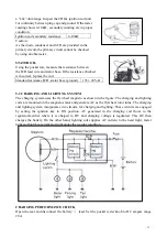
The charging system uses the flywheel magneto as shown in the figure. The charging and lighting
coils are mounted on the magneto stator and generate AC as the flywheel rotor turns. The charging
and lighting system incorporates two circuits, for charging and lighting. These circuits are engaged
by setting the ignition key to ON position. AC generated in the charging coil flows to the
regulator/rectifier where it is charged to DC and charging voltage is regulated. This DC then
charges the battery. On the other hand, lighting coil supplies AC current to the head light, meter
light and high beam indicator light under the regular condition.
CHARGING PERFORMANCE CHECK
Open the seat and disconnect the battery
○
-
lead. Set the pocket tester knob to DC ampere range
20A.
- 31 -

