10GBASE-KR Ethernet TRD
73
UG1058 (v2017.1) April 19, 2017
Chapter 5:
Reference Design Details
Then it stores the data on the control computer in a text file through the USB-JTAG
connection (U80) on the KCU1250 board.
For more details on the MicroBlaze processor core, see the MicroBlaze Soft Processor Core
website
AXI Interconnect
The AXI interconnect allows multiple AXI masters (MicroBlaze processor subsystem and
JTAG to AXI Master) to communicate with multiple AXI slaves (AXI DRP Bridge and AXI
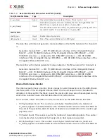
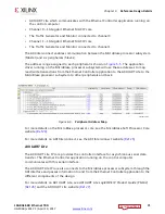
BRAM Controller). The address map for the AXI slaves is shown in
For more details on the AXI Interconnect, see the AXI Interconnect website
Clocking and Reset
The 10-Gigabit Ethernet PCS/PMA core requires a 156.25 MHz differential reference clock
for the GTH transceivers. The shared logic (clocking and reset logic) within the channel 0
10-Gigabit Ethernet PCS/PMA IP core produces a single ended 156.25 MHz clock. This clock
is used by the 10-Gigabit Ethernet MAC and Traffic generator on Channel 0. A similar clock
circuit is implemented for Channel 1. The MicroBlaze processor subsystem is driven by the
X-Ref Target - Figure 5-6
Figure 5-6:
AXI Slaves Address Map in the Eye Scan System
X18484-120716


