


10GBASE-KR Ethernet TRD
64
UG1058 (v2017.1) April 19, 2017
Chapter 5:
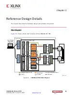
Reference Design Details
The details of the hardware architecture are provided in three sections:
•
: Describes the 10-Gigabit Ethernet PCS/PMA IP core
(10GBASE-KR), 10-Gigabit Ethernet MAC IP core (10G MAC) and the Traffic Generator
and Monitor.
•
: Describes the MicroBlaze™ processor subsystem and the
peripherals connected to it.
•
Describes the MicroBlaze processor subsystem and JTAG
to AXI Master IP core that communicate with the DRP port of the transceivers to collect
data samples and create an eye diagram.
•
: Describes how clocks and resets are distributed to the different
components in the 10GBASE-KR TRD.
Data Plane Components
The 10-Gigabit Ethernet PCS/PMA IP (10GBASE-KR) and 10-Gigabit Ethernet MAC IP (10G
MAC) cores constitute a 10 Gb/s Ethernet channel. There are two channels in the
10GBASE-KR TRD; channel 0 and channel 1. The data source for each channel is a Traffic
Generator implemented in the FPGA that drives the 10G Ethernet MAC.
10-Gigabit Ethernet PCS/PMA IP Core
The 10-Gigabit Ethernet PCS/PMA (10GBASE-KR) IP core provides an XGMII interface to
connect to a 10-Gigabit Ethernet MAC IP core and implements a 10.3125 Gb/s serial
single-channel PHY (GTH transceiver) brought out to TXN/TXP and RXN/RXP I/O pins that
are connected to differential SMA connector pairs on the board. SMA cables connect these
signals to the backplane.
The 10GBASE-KR IP core is configured to support auto negotiation (AN) and forward error
correction (FEC). The MDIO interface is disabled and configuration and status vectors are
used to manage the core.
A license can be obtained at the 10 Gigabit Ethernet PCS/PMA with FEC/Auto-Negotiation
(10GBASE-KR) website
. More information is available in the
10G Ethernet PCS/PMA
LogiCORE IP Product Guide
(PG068)
.
Relevant bits of the configuration and status vectors are brought out to Virtual
Input/Output (VIO) IP cores to configure and monitor the IP. The training port of the
10-Gigabit Ethernet PCS/PMA is also connected to a VIO IP core to access the transceiver's
DRP address map.
More VIO IP core information is available at the Virtual Input/Output (VIO) website
and in the
Virtual Input/Output LogiCORE IP Product Guide
(PG159)
. Details about
the DRP address map is available in
UltraScale Architecture GTH Transceivers User Guide
(UG576)