


Phaser 6130 Color Laser Printer Service Manual
8-17
Service Parts Disassembly
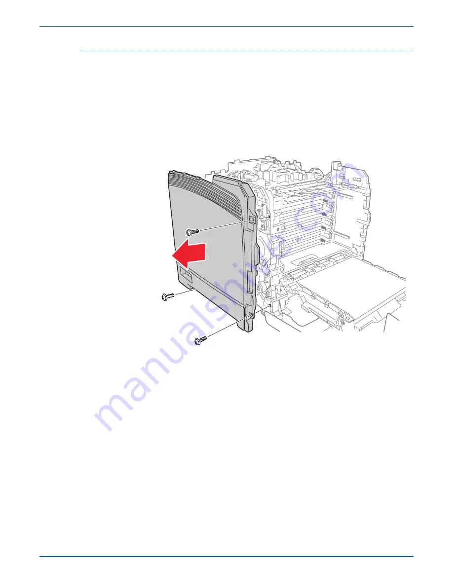
Left Side Cover
(PL1.1.20)
1.
Remove the Rear Tray Cover (page 8-12).
2.
Remove the Top Cover (page 8-14).
3.
Remove the three screws (silver, tap, 8mm) that attach the Left Side
Cover to the printer.
4.
Release the hook at the front of the Left Side Cover.
5.
Carefully rotate the Left Side Cover to release the rear hooks.
6.
Remove the Left Side Cover from the printer.
s6130-144
Содержание PHASER 6130
Страница 1: ...Service Manual Phaser 6130 701P47121 Color Laser Printer...
Страница 2: ......
Страница 14: ...xii Phaser 6130 Color Laser Printer Service Manual...
Страница 50: ...28 Phaser 6130 Color Laser Printer Service Manual General Information...
Страница 102: ...2 52 Phaser 6130 Color Laser Printer Service Manual Theory of Operation...
Страница 240: ...4 56 Phaser 6130 Color Laser Printer Service Manual General Troubleshooting...
Страница 301: ...6 Chapter Adjustments and Calibrations In this chapter Adjustments Calibrations Parameter Setting...
Страница 310: ...6 10 Phaser 6130 Color Laser Printer Service Manual Adjustments and Calibrations...
Страница 311: ...7 Chapter Cleaning and Maintenance In this chapter Service Maintenance Procedure Cleaning Maintenance...
Страница 314: ...7 4 Phaser 6130 Color Laser Printer Service Manual Cleaning and Maintenance...
Страница 435: ...A Appendix Reference Contents Phaser 6130 Menu Map Firmware Update Acronyms and Abbreviations...
Страница 452: ...I 8 Phaser 6130 Color Laser Printer Service Manual Index...
Страница 453: ......
Страница 454: ...701P47121...


