


Installation and Configuration
Initial Inspection
Release 1.2
17
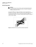
Figure 2.2
RS-232 Interface Subplate
(Located on Power Supply Rear Panel)
!
CAUTION
Use proper static control techniques to avoid damage to static-sensitive components
on the printed circuit board
S1 Switch
1 Remote/Local Startup
2 Power On Service Request
(Enable/Disable)
3 Not Used
4-8 Primary Address
Selection (A1-A5)
Switch Position
Reference markings
(0) (1)
Error LED (ERR)
Indicates that a programming
error has occurred. Clear with
error query command.
J21 User Signal
Connector
IEEE 488 Connector
Address LED (ADR)
Indicates that the unit is
being addressed by the
master controller.
Содержание RS232-XPD
Страница 1: ...Operating Manual Internal RS 232 Interface for XPD Series Programmable DC Power Supply RS232 XPD ...
Страница 2: ......
Страница 3: ...Operating Manual for Internal RS 232 Interface for XPD 500 Watt Series Programmable DC Power Supply ...
Страница 10: ...About This Manual viii Operating Manual for RS 232 for XPD Series Power Supply ...
Страница 16: ...Features and Specifications Specifications 14 Operating Manual for RS 232 for XPD Series Power Supply ...
Страница 59: ......


