background image

14

www.xa.com/en

Power On/Off

When the remote controller is off, long press the power button for at least 2 seconds until all the 

indicators flash with green light simultaneously, followed by another long press until the speaker beeps 

and the second indicator goes flashing green. When it turns solid green, the remote controller turns on.

When the remote controller is on, long press the power button for at least 2 seconds until all the 

indicators flash with green light simultaneously, followed by another long press until the screen reads 

"Powering Off" and the second indicator goes flashing green. When the speaker beeps, the remote 

controller turns off.

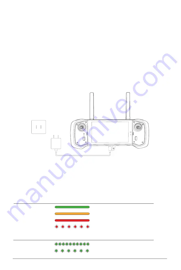
Charge Remote Controller

Insert the Type-C end into the charging port of the remote controller, and the USB end into the

adapter, and then connect to a power source. The first indicator is flashing green when charging begins. 

It turns solid green when the remote controller is fully charged.

Indicator

The first indicator (the upper one) indicates the battery level or charging status.

During ordinary use of the remote controller, you can check the battery level by observing the first 

indicator or dragging down from the top of the screen.

When the remote controller is off, you can check the battery level by short pressing the power button 

and observing the first indicator.

While charging the remote controller, you can check the battery level by observing the first indicator.

Battery Level LED Behavior 


              Description

Solid Green
Solid Yellow
Solid Red
Slow Flashing Red

Charging LED Behavior 


               Description

Fast Flashing Green
Slow Flashing Green

Fast Charging
Slow Charging

30%~100%
10%~29%
5%~9%
0%~4%

Содержание M500 Remote Sensing UAS

Страница 1: ...User Manual M500 Remote Sensing UAS EN Version 1 0 ...

Страница 2: ...ty purposes and better user experience it is highly recommended that you read this manual carefully and strictly follow the instructions hereof Contact Us If you have any questions about this document please contact our Technical Support team via email info xa com ...

Страница 3: ...e Avoidance Radar System 5 Terrain following Radar System 6 Imaging System 6 Aircraft 7 Unfold Aircraft 7 Unfold Landing Gears 7 Install Camera 8 Install Battery 9 Smart Battery 10 Power On Off 10 Check the Battery Level 10 Charge the Battery 11 Remote Controller 13 Diagram 13 Power On Off 14 Charge Remote Controller 14 Unfold Antennas 15 Install USB Wireless Modem 16 Joystick Mode 19 ...

Страница 4: ... Xpilot App 20 App Overview 20 Appendix 22 Status Indicator 22 Specifications 23 ...

Страница 5: ... aircraft and inspections of the remote controller motors and other modules Here are 8 rules that MUST be strictly followed during the flight 1 NEVER fly over highways railway stations subways or areas surrounded by tall buildings 2 NEVER fly near or over designated national security sensitive locations such as military bases borders and airports 3 NEVER fly over national political and diplomatic ...

Страница 6: ...tion Manual Also XAG shall not be liable for any indirect consequential punitive accidental special or exemplary damages including any loss incurred as a result of your purchase use or inability to use the product even if user have been advised of the possibility of such loss 7 To the maximum extent permitted by law under any circumstances the liability or compensation amount from XAG to you for a...

Страница 7: ...uper fast map generation in the cloud and local server inside the drone it offers you instant access to an HD map Besides more application scenarios and operation modes are supported as it fits a replaceable standard mounting interface allowing for other payload sensors such as XCam 20 Pro Gimbal Camera and Multi spectral Gimbal Camera List of Items Please see that all the following items are pres...

Страница 8: ... 8 Landing Gear Fastener 9 2 4 5 8GHz Antenna 10 Camera 11 SIM Card Slot 12 Extension Interface 13 4G Antenna 14 Battery Snap Fit 15 Dual camera System 16 Status Indicator 17 2 4 5 8GHz Antenna 18 Landing Gear 19 Extension Interface 20 Flight Indicator 21 Power Button 22 Cover 23 Smart Battery 24 Arm Fastener 14 11 24 19 20 21 22 23 16 10 13 12 17 15 9 8 18 1 2 5 4 6 3 7 ...

Страница 9: ...ission via WiFi 4G dual path In case of failure to receive differential signals PPK is available to support aerial mapping For areas not covered by the XAG Cloud RTK network you may configure via the App to get access to Qianxun network or CORS network to start the mission Besides if anything goes wrong with the RTK positioning system the GNSS positioning system essentially a backup GNSS module of...

Страница 10: ...op detection via XAI Smart Agricultural System the map can be imported to an XAG agricultural drone for autonomous plant protection A built in 1 inch 20MP CMOS sensor brings about high resolution imaging while the mechanical global shutter sees that photos are free from distortion fuzziness or rolling shutter effect Keeping time with RTK information it synchronizes the photo and location informati...

Страница 11: ...ft Unfold Aircraft Spread out the arms as shown below until you hear a click Unfold Landing Gears Spread out the landing gears as shown below until you hear a click Please see that the landing gears are securely locked Note ...

Страница 12: ...e clockwise until the white dot is aligned with the lock mark Please switch off the aircraft before fitting removing the camera or it may cause damage to the components Please switch off the aircraft before inserting removing SIM card and SD card Otherwise the SIM card will locked or the SD card will be damaged Note White Dot ...

Страница 13: ...l you hear a click Please make sure that the battery is firmly inserted before the flight Otherwise it will result in sudden power loss during the flight and cause an accident Beware of the travel switch when handling and storing the battery separately Note Travel Switch ...

Страница 14: ...l safety of the load side There is one power button and four indicators shown as follows Power On Off Upon connection to the aircraft or the charger long press the power button for at least 1 second until all the battery level indicators flash simultaneously followed by the other long press for at least 1 second until the battery beeps and all the status indicators are on off Then the battery turn...

Страница 15: ...100 LED Behavior Status Description 1 Flashing Light 1 Solid Light 2 Solid Lights 3 Solid Lights 4 Solid Lights 2 Double Flashing Lights 3 Double Flashing Lights Auto Lock Remote Lock Locking for low battery it will automatically unlock after being charged voltage over 3 2V Battery locks remotely Please contact tech support to unlock it LED Behavior Status Description Solid White Fast Flashing Red...

Страница 16: ... or apply pressure to it Please see that the battery interface is clean and free from metal parts After use please charge the battery to 40 60 before storage Avoid storing the battery below 10 or above 45 Store the unused battery in a cool dry place Fully discharge and recharge it every 90 days to maintain battery health NEVER expose the battery to harsh sunlight or rain NEVER charge the battery w...

Страница 17: ...er Diagram Antenna Left Front Button Right Front Button Strap Ring Hover Return Joystick Indicator Photo Video Charging Port Air Inlet USB Wireless Modem Cover TypeC TF CARD HDMI Interface Air Outlet Screen Camera Power Button Speaker ...

Страница 18: ...ort of the remote controller and the USB end into the adapter and then connect to a power source The first indicator is flashing green when charging begins It turns solid green when the remote controller is fully charged Indicator The first indicator the upper one indicates the battery level or charging status During ordinary use of the remote controller you can check the battery level by observin...

Страница 19: ...r the lower one shows the current status The table below describes its behavior When the remote control is updating both indicators are on which is described as follows Status LED Behavior Description Solid Green Flashing Green Solid Red Normal Powering on off Abnormal Update LED Behavior Description Solid Red Updating ...

Страница 20: ...optimum signal coverage is shown as below Note Install USB Wireless Modem Insert the SIM card into the USB wireless modem Open the USB wireless modem cover insert the modem and close the cover firmly Please switch off the aircraft before inserting removing SIM card and SD card Otherwise the SIM card will locked or the modem will be damaged Note ...

Страница 21: ...ress quickly Short press the Right Front Button to rotate the camera upward slowly while long press quickly Photo Video Short press the Photo Video Button to take a photo while long press a video Right Front Button Left Front Button Photo Video Start Motors Before a flight push both the joystick and the throttle as below to start the motor If you fail to push the throttle within 3 seconds after re...

Страница 22: ...er the aircraft lands pull the throttle to the lowest position and hold it until the motors stop Hover Return During the flight short press the Hover Return button to hover the aircraft while long press to have it return Hover Return ...

Страница 23: ...de 3 the factory default control mode Note Left Joystick Forward Turn Left Turn Right Right Joystick Ascend Descend Left Right Left Joystick Ascend Descend Turn Left Turn Right Right Joystick Left Right Left Right Backward Left Joystick Right Joystick Turn Left Turn Right Ascend Descend Japanese Hand Mode 1 American Hand Mode 2 Chinese Hand Mode 3 Forward Backward Forward Backward ...

Страница 24: ...eived Single indicates single point signal only GPS signal available no differential data None indicates no signal no GPS signal or insufficient satellites 4 Switch Device Tap to switch to another device 5 Flight Screen Tap to enter the flight screen 7 Mission Screen Tap to enter the flight mission screen 8 Flight Results Tap to view flight results 9 User Profile Tap to view user profile 10 Battey...

Страница 25: ...nstable shared GPS signal as well as differential data received None indicates no signal no GPS signal or insufficient satellites 6 Camera Status Connection status of the camera and the number of photos taken 7 8 Flight Commands Tap to hover or return 9 Flight View Tap to switch video transmission images 10 11 12 13 Flight Status Current altitude vertical speed flight distance and horizontal speed...

Страница 26: ... Status Description Weak GPS signal or compass interference Strong GPS signal GPS route mode Fly in safe mode Low battery voltage or low single cell voltage FC initialization or self inspection failure when powered on Flight Control formatted or incorrect parameters Propulsion system error IMU Failure Sensor except IMU error GPS malfunction or low heading accuracy Manual Mode Auto Mode Status Erro...

Страница 27: ...oidance Radar 30m Ranging Distance of Binocular Vision 10m Specifications Aircraft Model M500 Remote Sensing UAS Takeoff Weight 2 55kg Wheelbase 492mm Max Takeoff Altitude 6000m Max Ascent Velocity 4m s Max Descent Velocity 3m s Max Horizontal Speed 10km h Route Mode Max Slope 25 Max Angular Velocity 170 S Duration of Flight Max 35 Minutes Operating Frequency 2 400 GHz to 2 483 GHz Europe Japan So...

Страница 28: ...n illustrations photos methods processes etc belongs to Guangzhou Xaircraft Technology CO LTD and is protected by copyright law Without written authorization no individual or institution is allowed to reproduce extract translate distribute or otherwise reproduce or quote any content hereof This manual is subject to update without prior notice ...

Отзывы: