-
If the peak is assembled over the visor, check the proper functioning of the
visor itself by lifting up and lowering it completely.
•
VISOR
4
Visor Disassembly
To disassemble the visor, first remove the peak if assembled (see instructions above).
4.1
Open the visor completely.
4.2
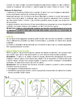
Press and hold the visor release button (A) down and slide the visor forward
until it clicks (Fig. 4).
4.3
Free the visor fastenings (B1 e B2) from their housing (Fig. 5).
4.4
Follow the same steps on the other side of the helmet.
5
Visor Assembly
5.1
Set the visor in open position by placing the visor fastenings (B1 and B2) in line
with the housings in the visor mechanism (Fig. 5).
5.2
Insert fastening B1 in the provided housing and press the visor against the
shell in line with fastening B2. This will push the visor release button (A).
5.3
Slide the visor backwards until the visor release button (A) clicks.
5.4
Follow the same steps on the other side of the helmet.
5.5
Close the visor completely.
6
Visor Mechanism Adjustment
The visor mechanism is equipped with a visor clearance adjusting system that ensu-
res that the visor is lowered effectively against the window trim. This is why the
mechanism’s support has an upper and lower reference tooth. The helmet is delive-
red with a correctly adjusted system. When using the helmet, regularly check that the
visor adheres perfectly and is in line with the deformable lip of the window trim when
it is lowered all the way. If this is not the case, proceed as follows:
6.1
Disassemble the peak (if assembled) and then the visor (see instructions
above) and check in which position of the upper reference C1 and lower refe-
rence C2 teeth the mechanism is located (Fig. 6).
6.2
Loosen the two screws D1 and D2 on the visor mechanism using a 2.5 mm
Allen wrench.
6.3
Lift the mechanism from its support and move it forwards or backwards accor-
ding to the adjustment to be made. Then lower the mechanism into its support
so that the upper C1 and lower C2 adjustment teeth are in the same position.
6.4
Tighten both screws D1 and D2.
6.5
Follow the same steps on the other side of the helmet.
6.6
Assemble the visor (see instructions above).
6.7
Check contact between the visor and the trim.
WARNING
-
Make sure that the mechanisms are working properly. Open and close the
visor, making sure that the mechanisms hold it in the different positions. If
necessary, repeat the above-mentioned steps.
-
Do not use the helmet if the visor has not been assembled properly.
-
Do not remove the side mechanisms from the shell.
15
Содержание X-551GT
Страница 82: ...82 design A...
Страница 83: ...83 E v A...
Страница 90: ...90 12 12 1 15 12 2 16 12 3 13 13 1 13 2 16 VPS 12 2 13 2 13 3 15 14 14 1 14 2 14 14 3 13 14 4 30 C...
Страница 91: ...91 X 551 GT 17 VPS 18 19 20 21 N COM NOLAN COMMUNICATION SYSTEM X Lite N Com N Com N Com N Com...
Страница 92: ...Fig 4 Fig 5 Fig 2 Fig 3 Fig 6 B1 B2 C1 D2 D1 C2 A Fig 1 B 1 2 A B A...
Страница 93: ...MIN MAX Fig 8 Fig 9 Fig 7 Fig 10 B Fig 10 A A B B C Fig 12 Fig 11...
Страница 94: ...Fig 13 Fig 14 Fig 15 Fig 16 Fig 17 Fig 18...
Страница 95: ...Fig 19 Fig 20 Fig 21...


