


13
US/CAN/MEX: +1-518-289-1294 Toll Free Technical Support: +1-844-280-WYRE (9973)
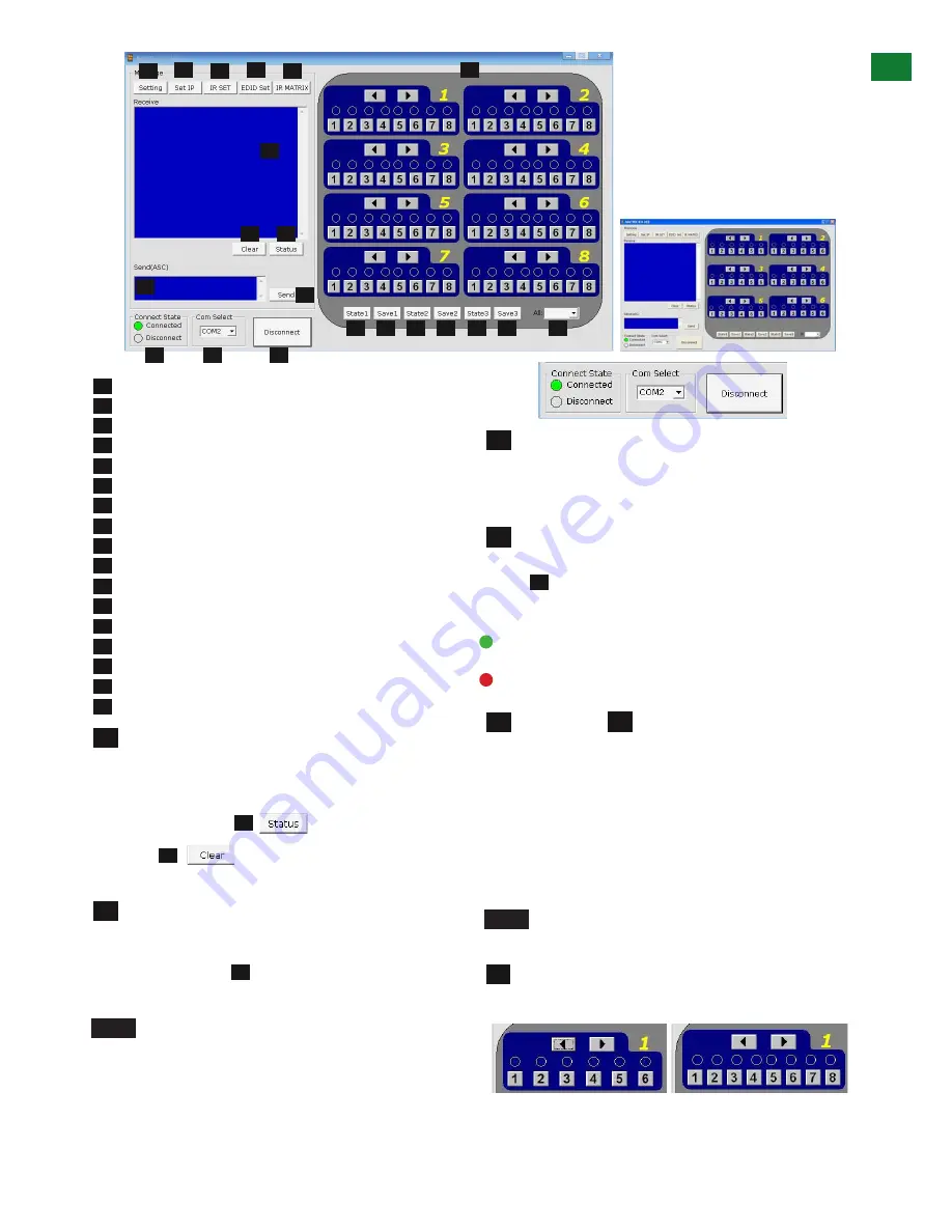
Receive Message Window
Matrix Status
Message Clear
Send Message Window
Send Message Button
Com Port Connect State
Com Port Select
Connect/Disconnect from Matrix
Input/Output Switch area
Select Presaved Output State 1, 2, or 3
Save Current Output State 1, 2, 3
Select all Inputs/Outputs
Settings
Set IP access
IR Set Area
EDID Settings
IR Matrix
Receive Message Window
– displays messages
received from the matrix, such as input/output settings
and command selections.
You can view the current condition of all input/output
ports by pressing the
button.
Pressing
will delete the previous message
received in the window.
Send Message Window
- Input your serial
commands for the matrix in the
Send Message Window
- such as instructions for outputs or to enter update
mode – and click the
Send
button to deliver the
message to the Matrix. The control command uses ASCII.
NOTE
To see the firmware version currently used in
the system – power off and repower while the matrix
is connected to COM CTL. The firmware version and
creation date will be displayed together with the
normal output state of the matrix.
Com Connect State
- Shows if the matrix is
connected
or
disconnected
to the
Com Port
and
communication is enabled. Selection between ports is
available by pressing the
Com Port Select
button.
When
connected
, the only option will be to
Disconnect
and vice versa.
Press to connect/disconnect the matrix from the
software control.
Connected
to ENABLE matrix communication
Disconnected
to DISABLE matrix communication
Com Select Connect/Disconnect
Click the Com Select dropdown to see all Com ports
available. Select your chosen Com port number and
press the CONNECT button. You will notice the button
change to show ‘disconnect’ and CONNECT STATE
change to green for ‘connected’. Pressing the button
again will disconnect the Com port and the CONNECT
state will show red.
NOTE
The Com Select drop box offers options of
Com Ports to connect to – COM 1-10
Input/Output Switch
- Switches connected inputs
per output. Operation as with remote control handset.
1
1
2
2
2
3
3
3
4
4
5
5
5
6
6
7
7
8
8
8
9
9
10
10
10
10
11
11
11
11
12
12
13
13
14
14
15
15
16
16
17
17
1
4
7
7
6
8
9
MX-0606-PP
MX-0808-PP
MX-0808-PP
MX-0606-PP
14
Technical Support: [email protected] US: +866 677 0053 EU: +44 (0) 1793 230 343
ADV
AN
CE
D OPE
RA
TI
ON
13
01
Receive Message Window
02
Matrix Status
03
Message Clear
04
Send Message Window
05
Send Message Button
06
Com Port Connect State
07
Com Port Select
08
Connect/Disconnect from Matrix
09
Input/Output Switch area
10
Select Presaved Output State 1, 2, or 3
11
Save Current Output State 1, 2, 3
12
Select all Inputs/Outputs
13
Settings
14
Set IP access
15
IR Set Area
16
EDID Settings
17
IR Matrix
MX0808-PP
MX0606-PP
14 15 16 17
01
03 02
05
04
06
07
08
10 11 10 11 10 11
12
09
01
Receive Message Window
– displays messages received
from the matrix, such as input/output settings and command
selections.
You can view the current condition of all input/output ports
by pressing the button.
Pressing will delete the previous message
received in the window.
04
Send Message Window
- Input your serial commands
for the matrix in the
Send Message Window
- such as
instructions for outputs or to enter update mode – and click
the
Send
button to deliver the message to the Matrix.
The control command uses ASCII.
NOTE
To see the firmware version currently used in the
system – power off and repower while the matrix is connected
to COM CTL. The firmware version and creation date will be
displayed together with the normal output state of the matrix.
03
02
05
06
Com Connect State -
Shows if the matrix is
connected
or
disconnected
to the
Com Port
and communication is
enabled. Selection between ports is available by pressing the
Com Port Select
button.
07
When
connected,
the only option will be to
Disconnect
and
vice versa.
Press to connect/disconnect the matrix from the
software control.
•
Connected
to ENABLE matrix communication
•
Disconnected
to DISABLE matrix communication
Com Select Connect/Disconnect
k the Com Select dropdown to see all Com ports available. Select
your chosen Com port number and press the CONNECT button.
You will notice the button change to show ‘disconnect’ and
CONNECT STATE change to green for ‘connected’. Pressing the
button again will disconnect the Com port and the CONNECT state
will show red.
NOTE
The Com Select drop box offers options of Com Ports
to connect to – COM 1-10
09
Input/Output Switch
- Switches connected inputs per
output. Operation as with remote control handset.
08
07
08
A large yellow number denotes each OUTPUT section with
INPUTS chosen by either clicking the left/right arrow buttons
to scroll through inputs numerically or by pressing the input
numbers below.
The INPUT/OUTPUT switch allows output port selection
(display) and Input port select (source) buttons for specific
MX0808-PP
MX0606-PP
14
Technical Support: [email protected] US: +866 677 0053 EU: +44 (0) 1793 230 343
ADV
AN
CE
D OPE
RA
TI
ON
13
01
Receive Message Window
02
Matrix Status
03
Message Clear
04
Send Message Window
05
Send Message Button
06
Com Port Connect State
07
Com Port Select
08
Connect/Disconnect from Matrix
09
Input/Output Switch area
10
Select Presaved Output State 1, 2, or 3
11
Save Current Output State 1, 2, 3
12
Select all Inputs/Outputs
13
Settings
14
Set IP access
15
IR Set Area
16
EDID Settings
17
IR Matrix
MX0808-PP
MX0606-PP
14 15 16 17
01
03 02
05
04
06
07
08
10 11 10 11 10 11
12
09
01
Receive Message Window
– displays messages received
from the matrix, such as input/output settings and command
selections.
You can view the current condition of all input/output ports
by pressing the button.
Pressing will delete the previous message
received in the window.
04
Send Message Window
- Input your serial commands
for the matrix in the
Send Message Window
- such as
instructions for outputs or to enter update mode – and click
the
Send
button to deliver the message to the Matrix.
The control command uses ASCII.
NOTE
To see the firmware version currently used in the
system – power off and repower while the matrix is connected
to COM CTL. The firmware version and creation date will be
displayed together with the normal output state of the matrix.
03
02
05
06
Com Connect State -
Shows if the matrix is
connected
or
disconnected
to the
Com Port
and communication is
enabled. Selection between ports is available by pressing the
Com Port Select
button.
07
When
connected,
the only option will be to
Disconnect
and
vice versa.
Press to connect/disconnect the matrix from the
software control.
•
Connected
to ENABLE matrix communication
•
Disconnected
to DISABLE matrix communication
Com Select Connect/Disconnect
k the Com Select dropdown to see all Com ports available. Select
your chosen Com port number and press the CONNECT button.
You will notice the button change to show ‘disconnect’ and
CONNECT STATE change to green for ‘connected’. Pressing the
button again will disconnect the Com port and the CONNECT state
will show red.
NOTE
The Com Select drop box offers options of Com Ports
to connect to – COM 1-10
09
Input/Output Switch
- Switches connected inputs per
output. Operation as with remote control handset.
08
07
08
A large yellow number denotes each OUTPUT section with
INPUTS chosen by either clicking the left/right arrow buttons
to scroll through inputs numerically or by pressing the input
numbers below.
The INPUT/OUTPUT switch allows output port selection
(display) and Input port select (source) buttons for specific
MX0808-PP
MX0606-PP
ADV
ANCED OPERA
TION


