


17
US/CAN/MEX: +1-518-289-1294 Toll Free Technical Support: +1-844-280-WYRE (9973)
17
Technical Support: [email protected] US: +866 677 0053 EU: +44 (0) 1793 230 343
ADV
AN
CE
D OPE
RA
TI
ON
A
Receives the specific IR code used to operate the Matrix via
remote control. Can contain a
custom
or
data code
. Third
party remote control codes are also shown.
B
IR code can also be input manually in the event it is
unreadable.
01
Press to automatically
read
the current IR code from the
device.
01
The resulting code appears in the
wait to modify code
section
where
output
and input code can be edited if
necessary (for example if using third party control systems
NOTE
Modified code can be saved as a Custom code
and read directly from a library of stored custom codes.
All code should be different.
03
Write the code from the Modify section to the device to
authorise remote control usage.
NOTE
All input/output boxes should contain code. If
inputting manually, make sure there is no repetition of
code.
Modify Section - Control Commands and Code
Code input in the
Input/Output
section and
Control
code
section must follow a strict format for the
command to be understood by the system.
For reference - the command format to be input is:
Type
“Cir”
- followed by a
“space”
- then the
“code
number”
– and hit the
”enter”
key.
For example Cir 39 + ”enter”
(equals a hex code of 63 69
72 20 33 39 0D 0A)
Such a command will tell the matrix to select the next
Input
source
for
Output 4
B
02
04
MX0606/0808-PP Control Code
Output 1
<”08”
“09”>
1 ”00”
2 ”01”
3 ”02”
4 ”03”
5 ”04”
6 ”05”
7 ”06”
8 ”07”
Output 2
<”18”
“19”>
1 ”10”
2 ”11”
3 ”12”
4 ”13”
5 ”14”
6 ”15”
7 ”16”
8 ”07”
Output 3
<”28”
“29”>
1 ”20”
2 ”21”
3 ”22”
4 ”23”
5 ”24”
6 ”25”
7 ”26”
8 ”27”
Output 4
<”38”
“39”>
1 ”30”
2 ”31”
3 ”32”
4 ”33”
5 ”34”
6 ”35”
7 ”36”
8 ”37”
Output 5
<”48”
“49”>
1 ”40”
2 ”41”
3 ”42”
4 ”43”
5 ”44”
6 ”45”
7 ”46”
8 ”47”
Output 6
<”58”
“59”>
1 ”50”
2 ”51”
3 ”52”
4 ”53”
5 ”54”
6 ”55”
7 ”56”
8 ”57”
Output 7
<”68”
“69”>
1 ”60”
2 ”61”
3 ”62”
4 ”63”
5 ”64”
6 ”65”
7 ”66”
8 ”67”
Output 8
<”78”
“79”>
1 ”70”
2 ”71”
3 ”72”
4 ”73”
5 ”74”
6 ”75”
7 ”76”
8 ”77”
If the control command is sent successfully, the current
output
state
selected will feedback to show the
in-put port
selected. The
return status format is as follows:
S
X1
X2
‘\r’
‘\n’
This translates as:
“S”
Output port
Input port
1st byte
2nd byte
3rd byte
For example: if
Cir 44 “enter”
is sent successfully to the matrix, it
will feedback
“s55”
– meaning
Output 5
has selected
Input 5
.
Read Status Command
The command length of the read status is 4 bytes. Type
“bc”
-
followed by a
“space”
- and hit the
“enter”
key.
For example:
bc + “enter”
NOTE
Such a command will tell the matrix to feedback the
current status of all outputs. See below for status format (16
bytes)
1
2
3
4
5
6
7
8
9
10
11
12
13
14
15
16
‘\r’
‘\n’
s
X1
X2
s
X3
X4
s
X5
X6
s
X7
X8
‘\r’
‘\n’
Each of the X1, X2, X3, X4, X5, X6, X7, X8 signifies the related
input as chosen by a
specific output:
X1 = Out-put
1, X2 = Output 2 etc. For example, a status reading of
“\r\ns12s22s53s45\r\n”
signifies the following matrix settings.
Output 1 Output 2 Output 3 Output 4 Output 5 Output 6 Output 7 Output 8
Input 1
Intput 2
Intput 3
Intput 4
Intput 5
Intput 6
Intput 7
Intput 8
03
EDID Set
MX0808-PP
1
1
2
2
3
5
16
3
4
A
MX-0606-PP
17
Technical Support: [email protected] US: +866 677 0053 EU: +44 (0) 1793 230 343
ADV
AN
CE
D OPE
RA
TI
ON
A
Receives the specific IR code used to operate the Matrix via
remote control. Can contain a
custom
or
data code
. Third
party remote control codes are also shown.
B
IR code can also be input manually in the event it is
unreadable.
01
Press to automatically
read
the current IR code from the
device.
01
The resulting code appears in the
wait to modify code
section
where
output
and input code can be edited if
necessary (for example if using third party control systems
NOTE
Modified code can be saved as a Custom code
and read directly from a library of stored custom codes.
All code should be different.
03
Write the code from the Modify section to the device to
authorise remote control usage.
NOTE
All input/output boxes should contain code. If
inputting manually, make sure there is no repetition of
code.
Modify Section - Control Commands and Code
Code input in the
Input/Output
section and
Control
code
section must follow a strict format for the
command to be understood by the system.
For reference - the command format to be input is:
Type
“Cir”
- followed by a
“space”
- then the
“code
number”
– and hit the
”enter”
key.
For example Cir 39 + ”enter”
(equals a hex code of 63 69
72 20 33 39 0D 0A)
Such a command will tell the matrix to select the next
Input
source
for
Output 4
B
02
04
MX0606/0808-PP Control Code
Output 1
<”08”
“09”>
1 ”00”
2 ”01”
3 ”02”
4 ”03”
5 ”04”
6 ”05”
7 ”06”
8 ”07”
Output 2
<”18”
“19”>
1 ”10”
2 ”11”
3 ”12”
4 ”13”
5 ”14”
6 ”15”
7 ”16”
8 ”07”
Output 3
<”28”
“29”>
1 ”20”
2 ”21”
3 ”22”
4 ”23”
5 ”24”
6 ”25”
7 ”26”
8 ”27”
Output 4
<”38”
“39”>
1 ”30”
2 ”31”
3 ”32”
4 ”33”
5 ”34”
6 ”35”
7 ”36”
8 ”37”
Output 5
<”48”
“49”>
1 ”40”
2 ”41”
3 ”42”
4 ”43”
5 ”44”
6 ”45”
7 ”46”
8 ”47”
Output 6
<”58”
“59”>
1 ”50”
2 ”51”
3 ”52”
4 ”53”
5 ”54”
6 ”55”
7 ”56”
8 ”57”
Output 7
<”68”
“69”>
1 ”60”
2 ”61”
3 ”62”
4 ”63”
5 ”64”
6 ”65”
7 ”66”
8 ”67”
Output 8
<”78”
“79”>
1 ”70”
2 ”71”
3 ”72”
4 ”73”
5 ”74”
6 ”75”
7 ”76”
8 ”77”
If the control command is sent successfully, the current
output
state
selected will feedback to show the
in-put port
selected. The
return status format is as follows:
S
X1
X2
‘\r’
‘\n’
This translates as:
“S”
Output port
Input port
1st byte
2nd byte
3rd byte
For example: if
Cir 44 “enter”
is sent successfully to the matrix, it
will feedback
“s55”
– meaning
Output 5
has selected
Input 5
.
Read Status Command
The command length of the read status is 4 bytes. Type
“bc”
-
followed by a
“space”
- and hit the
“enter”
key.
For example:
bc + “enter”
NOTE
Such a command will tell the matrix to feedback the
current status of all outputs. See below for status format (16
bytes)
1
2
3
4
5
6
7
8
9
10
11
12
13
14
15
16
‘\r’
‘\n’
s
X1
X2
s
X3
X4
s
X5
X6
s
X7
X8
‘\r’
‘\n’
Each of the X1, X2, X3, X4, X5, X6, X7, X8 signifies the related
input as chosen by a
specific output:
X1 = Out-put
1, X2 = Output 2 etc. For example, a status reading of
“\r\ns12s22s53s45\r\n”
signifies the following matrix settings.
Output 1 Output 2 Output 3 Output 4 Output 5 Output 6 Output 7 Output 8
Input 1
Intput 2
Intput 3
Intput 4
Intput 5
Intput 6
Intput 7
Intput 8
03
EDID Set
MX0808-PP
If the control command is sent successfully, the current
output state
selected will feedback to show the
input
port
selected. The return status format is as follows:
This translates as:
For example: if
Cir 44 “enter”
is sent successfully to the
matrix, it will feedback
“s55”
– meaning
Output 5
has
selected
Input 5
.
Read Status Command
The command length of the read status is 4 bytes. Type
“bc” - followed by a
“space”
- and hit the
“enter”
key.
For example:
bc + “enter”
NOTE
Such a command will tell the matrix to
feedback the current status of all outputs. See
below for status format (16 bytes)
Each of the X1, X2, X3, X4, X5, X6, X7, X8 signifies
the related input as chosen by a
specific output
: X1
= Output1, X2 = Output 2 etc. For example, a status
reading of
“\r\ns12s22s53s45\r\n”
signifies the following
matrix settings.
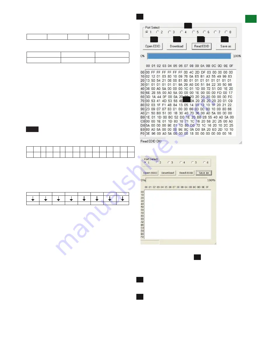
EDID Set
Pressing the
EDID SET
button in the
COM CTL
main screen allows user access to EDID settings that can
be read, saved and recalled.
Select your
OUTPUT
port (the output port is always
the first to be selected by default on entering
EDID
set)
Press
“Read EDID”
to read
EDID
from the selected
output port. The status bar shows the progress of the
EDID
read.
ADV
ANCED OPERA
TION


