10
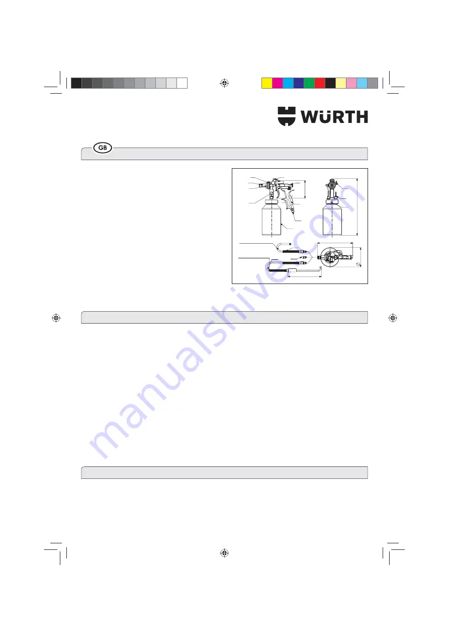
PARTS OF THE UNIT
1 UNION NUT
2 QUICK-ACTION COUPLING (CONNECTION 1)
3 RETAINER FOR QUICK-ACTION COUPLING
9 MATERIAL QUANTITY POSITION REGULATOR
10 HANDLE
11 HANGING
HOOK
19 MANUAL AIR SUPPLY REGULATOR
`q }¨¶{®®x ¿{}®})¿¡
26 TRIGGER
27 CUP
30 THREADED CONNECTION FOR PRESSURE CUP
36 MATERIAL APPLICATION NOZZLE
37 HOOK PROBE, 90° (fan jet) (Art. 0891 131)
38 NYLON PROBE, STRAIGHT (jet: 360°)
(Art. 0891 132)
41 SAFETY VALVE, 8 bar
1 – GENERAL WARNINGS
This symbol
attracts your attention to points which are very important for your safety.
Carefully read and follow the operating instructions before you use the spray gun.
Maintenance and repair work must be carried out by your sales partner during the warranty period. Failure to
do so will void your warranty.
Always disconnect the spray gun from the air supply before conducting repair work.
When selecting and before using the product you wish to apply with the gun, use the related safety data sheet
to ensure that it is compatible with the working environment and the individual safety devices.
When using the spray gun, please wear appropriate safety equipment (e.g. gloves, goggles, mask, overalls
etc.) and observe the instructions on the safety data sheet of the product to be applied.
The wearing of safety goggles is always recommended.
Hang the gun on the special hook when it is not in use to ensure that it remains in a vertical position. Both
during operation and when the spray gun is not in use, please make sure that the gun is never tilted at more
than a 45° angle to prevent disadvantageous soiling of the lines in the gun.
Keep the safety valve (41) clean and make sure that it does not become clogged by pulling on the ring by
hand to check the pressure increase in the tank.
2 – FOR YOUR SAFETY
DANGER OF FIRE OR EXPLOSION
Never use solvents and/or cleaning agents based on halogenated carbons (1.1.1 Ethyl trichloride, methyl
chloride etc.). These kinds of substances can cause corrosion on galvanized parts, which can even result in
2/,($+!++,(
mm
94
180 mm
mm
300
190.5 mm
102 mm
26
1
2
3
9
11
10
27
23
38
37
36
Total Length: 840 mm
Totale Length: 1300 mm
30
19
41
Fig. 1
BDA_Druckbecherpistole_HRS2.indd 10
14.03.13 13:28
Содержание 0891 130
Страница 81: ...81 3 3 3 q BDA_Druckbecherpistole_HRS2 indd 81 14 03 13 13 28...
Страница 82: ...82 41 3 q q q q q q 3 q q q 3 q Fill the material q BDA_Druckbecherpistole_HRS2 indd 82 14 03 13 13 28...
Страница 83: ...83 q q 3 q q 36 37 38 36 37 38 A q q q q q q q 3 _ 3 q BDA_Druckbecherpistole_HRS2 indd 83 14 03 13 13 28...
Страница 84: ...84 0 q 3 q q 3 q 9 9 BDA_Druckbecherpistole_HRS2 indd 84 14 03 13 13 28...
Страница 85: ...85 19 q 19 BDA_Druckbecherpistole_HRS2 indd 85 14 03 13 13 28...
Страница 86: ...86 3 3 BDA_Druckbecherpistole_HRS2 indd 86 14 03 13 13 28...
Страница 93: ...93 0 0 0 0 0 0 0 0 x 4 0 0 0 0 0 4 0 0 x 0 0 4 0 0 BDA_Druckbecherpistole_HRS2 indd 93 14 03 13 13 28...
Страница 122: ...122 BDA_Druckbecherpistole_HRS2 indd 122 14 03 13 13 28...
Страница 123: ...123 BDA_Druckbecherpistole_HRS2 indd 123 14 03 13 13 28...


