2.2.
Switch Modules
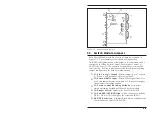
The RAB-14A can accept up to fourteen Switch Modules. Each
module includes a Common jack, jacks for “A” and “B” lines, a
Local A/B Switch, and a series of LED indicators.
À
Local A/B Switch:
Selects channel “A” or “B”, or selects
“X” (Remote) function. “X” position allows control by
Master Select Switch, ASCII commands, or signal level.
Á
“X” Indicator:
Lights when Local A/B Switch is set in
middle position. Indicates module is set for Gang Switch
Control, Local Signal Control, or ASCII Code Control.
Â
“A” Indicator:
Lights when data path is established
between Common port and port “A”.
Ã
“B” Indicator:
Lights when data path is established
between Common Port and port “B”.
Ä
RXD Indicator:
Lights when Common RXD line is high.
Å
TXD Indicator:
Lights when Common TXD line is high.
Æ
DTR Indicator:
Lights when Common DTR line is high.
Ç
CTS Indicator:
Lights when Common CTS line is high.
2-3
Unit Description
Figure 2.3: Switch Module Front Panel
Содержание RAB-14A
Страница 1: ...WTI Part No 12057 Rev B RAB 14A A B Switching System Preliminary Draft February 1997 User s Guide...
Страница 10: ...2 4 RAB 14A User s Guide...
Страница 26: ...A 2 Switch Module Apx 2 RAB 14A User s Guide Figure A 3 Switch Module Block Diagram...
Страница 28: ...jumpering J5 1 2 and 3 located on the Switch Module card Apx 4 RAB 14A User s Guide...

