


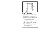


To daisy chain multiple RAB-14A rack units, proceed as follows:
1. Select one RAB-14A unit to serve as the Master Bank.
2.
Daisy Chaining:
Connect all banks using the supplied 14
pin ribbon cable(s).
a) Connect a cable from the Master Bank Control Module's
“OUTPUT” connector to the “INPUT” connector on the
first Satellite Bank Control Module.
b) Connect a cable from the first Satellite Bank Control
Module's “OUTPUT” connector to the “INPUT”
connector on the second Satellite Bank Control Module.
c) Repeat the procedure for each subsequent Satellite Bank.
Note that the “OUTPUT” connector on the last Satellite
Bank will remain unconnected.
3.
Set Bank Number:
Follow the criteria listed above, and use
SetUp Switches One through Four on each Control Module
to assign a Bank Number to each rack unit as described in
Section 3.1.1.
4.
Master / Satellite Designation:
Use SetUp Switch Nine on
each Control Module (Master
and
Satellite Banks) to
designate each rack unit as a Master or Satellite
(Section 3.1.6).
5.
Set Baud Rate, Parity, and Duplex:
Use the SetUp
switches on the Master Bank Control Module to select the
Baud Rate, Parity, and Duplex Mode as described in
Section 3.1. Note that these parameters only need to be set
for the Master Bank. The Baud Rate, Parity, and Duplex
Mode selected for the Master Bank will be applied to all
Satellite Banks.
6.
Cable Connection:
Connect A, B, and Common lines to the
appropriate connectors on each Switch Module.
7.
Power Connection:
Connect the power cable from each
Control Module to an appropriate power source.
8.
Switching Method:
Select a switching method, and
configure Switch Modules as described in Section 4.
3-5
Installation
Содержание RAB-14A
Страница 1: ...WTI Part No 12057 Rev B RAB 14A A B Switching System Preliminary Draft February 1997 User s Guide...
Страница 10: ...2 4 RAB 14A User s Guide...
Страница 26: ...A 2 Switch Module Apx 2 RAB 14A User s Guide Figure A 3 Switch Module Block Diagram...
Страница 28: ...jumpering J5 1 2 and 3 located on the Switch Module card Apx 4 RAB 14A User s Guide...