


3.2.
Switch Module Jumpers
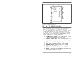
Each Switch Module includes a series of jumpers as shown in
Figure 3.1. These jumpers select the Switching Method,
DCE/DTE configuration and other features. Each module can be
configured for Gang Switch Control, Local Signal Control, or
ASCII Code Control. The function of each jumper is described
briefly below. Section 4 provides detailed information regarding
jumper configuration for each switching method.
À
J1; Pin 1 to Logic Ground:
When jumpered, pin 1 at ports
A, B, and C will be connected to logic ground.
Á
J2; External RS232 Input:
When Local Signal Control is
used, this jumper determines which A/C/B port will trigger
the automatic switching routine.
Â
J3; Switch Control (Switching Method):
Determines
which Switching Method will be used by this module.
Ã
J4; Disable Switch:
Disables the Local A/B Switch.
Ä
J5; Pull DTR/CTS/DCD High:
Allows the user to pull the
DTR, CTS, or DCD line high at the selected A/B Port.
Å
DCE/DTE Selection:
A Jumper Block which configures the
Common Port as either DCE or DTE.
3-3
Installation
Figure 3.1: Switch Module Jumpers
Содержание RAB-14A
Страница 1: ...WTI Part No 12057 Rev B RAB 14A A B Switching System Preliminary Draft February 1997 User s Guide...
Страница 10: ...2 4 RAB 14A User s Guide...
Страница 26: ...A 2 Switch Module Apx 2 RAB 14A User s Guide Figure A 3 Switch Module Block Diagram...
Страница 28: ...jumpering J5 1 2 and 3 located on the Switch Module card Apx 4 RAB 14A User s Guide...