Rev 10.3/10-16
16
MTCL8FS10TDC: #35079
If the lifter is equipped with a Remote Control System, press the transmitter power/enable button
and hold it briefly to activate the radio transmitter.
This button is also used to activate the
enable function (see T
O
R
ELEASE THE
P
ADS FROM THE
L
OAD
to follow).
Note: If the transmitter is activated, the transmission indicator light flashes green when any
button on the transmitter is pressed and held; if the transmitter is not activated, the indicator
light flashes red (see B
EFORE
U
SING THE
L
IFTER
: Preparing to Use the Optional Remote Control
System preceding).
Positioning the Lifter on the Load
Make certain that the contact surfaces of the load and all vacuum pads are free of any
contaminates that could prevent the pads from sealing against the load (see MAINTENANCE:
V
ACUUM
P
AD
M
AINTENANCE
).
To lift loads in the
flat orientation (see INTENDED USE: T
YPICAL
A
PPLICATIONS
), center the pad
frame to within 2" [5 cm] of the load center (hereafter, "on center"), since off-center loading can
cause the load to hang at an angle or to tilt unexpectedly (see T
O
T
ILT THE
L
OAD
to follow), and it
may also damage the lifter.
To lift loads in the
upright orientation (see INTENDED USE: T
YPICAL
A
PPLICATIONS
), center the pad
frame from left to right on the load and determine which will be the top edge of the load while
lifting. Then position the vacuum pads near that edge (hereafter, "above center"). This position
will maximize stability while lifting the load.
WARNING: When lifter is positioned above center, tilt latches must be locked
out before lifting load.
If the lifter is positioned above center on a load encountered in the flat orientation, the load
automatically tilts to the upright position when lifted (see T
O
T
ILT THE
L
OAD
: Tilting Loads
Positioned Above Center to follow). In this case, failure to lock out the tilt latches could result in
an unexpected load release or damage to the lifter.
Make sure that all vacuum pads will fit entirely on the load’s contact surface (see
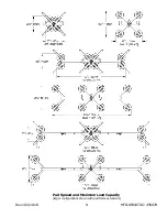
SPECIFICATIONS: Pad Spread) and that they will be loaded evenly while lifting (see
SPECIFICATIONS: Per-Pad Load Capacity). Then apply the lifter to the load so that all pads are
touching the contact surface.
WARNING: Lift point must be adjusted so as to prevent interference between
adjustable lift point tube and load.
Note: If the load would extend higher than the lift point when lifted or tilted upright, the lift
point must be adjusted to prevent interference between the adjustable lift point tube and the
load (see ASSEMBLY: T
O
S
ET UP THE
L
IFTER
). Failure to do so could damage the lifter or load, and
may result in an unexpected load release.
6
The radio transmitter turns off automatically, after a period of inactivity. The operator can also operate the lifter without using
the transmitter, if desired.
7
The lifter is designed to handle the maximum load weight (see SPECIFICATIONS: Maximum Load Capacity) when the load’s
center of gravity is positioned within 2" [5 cm] of the pad frame’s center point. Occasional loading deviations are permissible,
provided that the operator can maintain control of the load at all times and that the load weight is low enough to avoid damaging
the lifter.
Содержание MTCL8FS10TDC
Страница 2: ...View Quick Start Guide...
Страница 40: ...Rev 10 3 10 16 38 MTCL8FS10TDC 35079...
Страница 41: ...Rev 10 3 10 16 39 MTCL8FS10TDC 35079...
Страница 42: ...Rev 10 3 10 16 40 MTCL8FS10TDC 35079...
Страница 43: ...Rev 10 3 10 16 41 MTCL8FS10TDC 35079...
Страница 44: ...Rev 10 3 10 16 42 MTCL8FS10TDC 35079...
Страница 45: ...Rev 10 3 10 16 43 MTCL8FS10TDC 35079...
Страница 46: ...Rev 10 3 10 16 44 MTCL8FS10TDC 35079...

