5
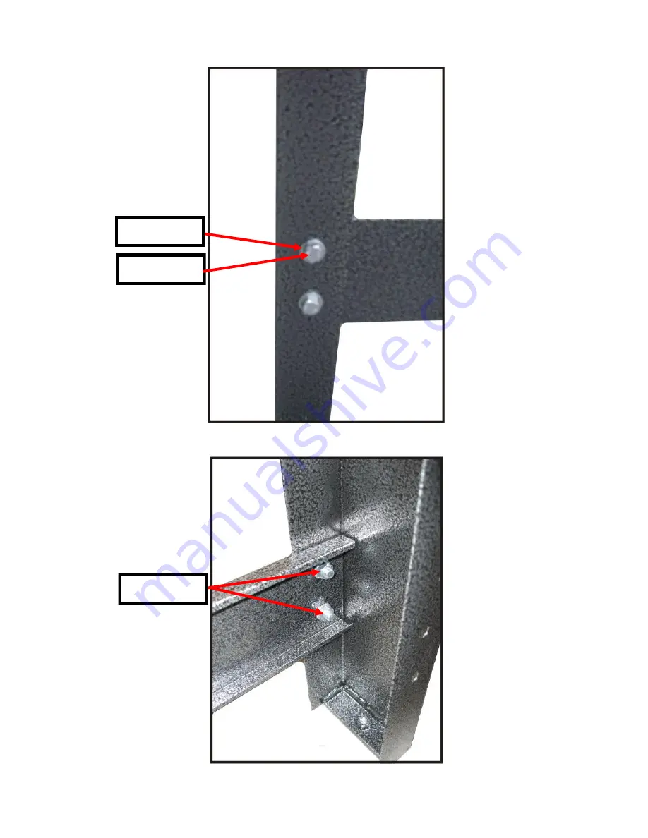
Leg to Cross Brace Assembly
Part
E
Flat Washer
D
Hex Bolt
F
Flange Nut
Inner Brace View
Страница 1: ...Mercury Compact Series REV 000...
Страница 2: ...2 Table of Contents Introduction 2 Standard Operating Guide 2 Features Specs 2 External Layout 3 8 Internal Layout 9 12 Wiring Diagram 13 F A Q 14 22 Comprehensive Parts List 23...
Страница 3: ...d is critical to ensure the quality of the print and to prevent the garments from burning The surface of the IR element can reach temperatures of 600 f with a curing temperature of 325 350 f The belt...
Страница 4: ...4 External Layout Leg All Part B Part A Cross Brace Part C Leveler Bolts Leg Assembly Cross Brace Leg Footing...
Страница 5: ...5 Leg to Cross Brace Assembly Part E Flat Washer Part D Hex Bolt Part F Flange Nut Inner Brace View...
Страница 6: ...6 Part D Hex Bolt Part E Flat Washer Part F Flange Nut Leg Attachment to Body Internal View of Leg Attachment at Body...
Страница 7: ...ail End Cap Part H Fender Washer Part I Acorn Nut Part J Drive Roller Part G Rail End Cap Part H Fender Washer Part I Acorn Nut Part L Driven Roller Drive Side Driven Side Part K Belt Part AP Rail Par...
Страница 8: ...8 Vent Door Vent Door Removed Part N Synch Knob Part O Vent Door Part M Screw Part C Hex Bolt Part P Hex Nut...
Страница 9: ...Speed Control Part T Cord Clamp Part U Power Cord 115V Part U Power Cord 115v Shown Above Nema 6 15p This plug is standard on all 230v models Shown Above Nema L5 30p This plug is standard on the 115V...
Страница 10: ...Block Part X Speed Control Board Top Cover Removal Main Circuit and Components Part AU Fan 220V WARNING RISK OF ELECTRICAL SHOCK Turn ALL power to unit OFF before service All service should be done b...
Страница 11: ...Control Part S Power Light Back of Control Panel Internal View of Element Part Y Silicone Grommet Part Z Inside Top Wall Part Y Silicone Grommet Part AB Element 115V Part AA Inner Side Wall Part AA I...
Страница 12: ...r Gearbox Internal View Part AE Chain Part AD Roller Sprocket Part AF Motor Sprocket Part M Screw Part AN Adjustment Stud Motor Only Part AT Chain Link Part AO Adjustment Stud Remaining 3 sides Motor...
Страница 13: ...Diagram 115 220V Mercury Compact Dryer NOTE The diagrams for the 115V and 220V models are the same with variations in the components only Shown Below with 115V components Power Cord Fan Element P N 39...
Страница 14: ...has come off it will need to be put back on however there is a reason it has come off Inspect the sprockets for damage or missing teeth the sprocket should look like the sprocket in Image 6 If sprocke...
Страница 15: ...View Image 8 Image 9 Image 10 2 The chain is on but my belt still won t turn Using a digital Volt Ohm meter in the VDC setting Image 11 check the voltage going to the belt motor The motor operates on...
Страница 16: ...ss of speed control setting its now time to open the top of the dryer There are 4 screws on the top and 2 on either side just above the vent doors lift off the top of the dryer and set it to the side...
Страница 17: ...out of Image 17 Image 17 Using the Digital meter in the VDC setting repeat the testing seen in images 11 and 12 Start at 0 and move the belt speed control to 100 if the full range of voltage 0 90vdc...
Страница 18: ...000 on a non auto ranging meter With the Red probe from the meter touch the circuit tab on L1 with the black probe touch the L2 Image 18 Image 18 Image 19 If the AC voltage coming into the board is co...
Страница 19: ...HITE wires can be seen connected to the switch Image 20 Using a digital Volt Ohm meter set the dial to the ACV setting ACV 200 1000 on a non auto ranging meter turn the dryer on and test the voltage a...
Страница 20: ...WHITE wires leading to the element For continuity the meter should have a low reading or produce a beep if the meter reads zero or doesn t produce a beep the element will need to be replaced Image 23...
Страница 21: ...res leading to the element Disconnect them from the terminal block Next locate the 4 nuts holding the element in place Image 25 Image 24 Image 25 Once the nuts are located loosen them to drop the elem...
Страница 22: ...lt tracks straight Do not over tighten the belt the belt should only be tight enough so it wont slip on the rollers Grasp the belt on both sides and pull on the belt Image 26 Once the belt tension is...
Страница 23: ...Light 76013 T Cord Clamp 39 76025 U Power Cord 115V 390663 V Fan 115V 31 76004 W Terminal Block 76117 X Speed Control Board 76194 Y Silicone Grommet 3759 Z Inside Top Wall 60261 AA Inner Side Wall 602...