13.1
Tell the user how to operate the appliance and hand over
the Users Instructions leaflet.
13.2
Tell the user what to do if the heating system is not to be
used in frosty weather.
13.3
Tell the user the sealed system set pressure.
13.4
Tell the user of the importance of regular servicing.
Worcester Heat Systems Ltd. offer a comprehensive maintenance
contract.
13.5
Set the system controls to the user’s requirements.
13.6
If an external programmer has been fitted which has a
programmable domestic hot water facility then it is suggested
that this be set to Continuous or the equivalent.
14.1 SERVICING
To ensure continued efficient operation of the appliance it must
be checked and serviced as necessary at regular intervals. The
frequency of servicing will depend upon the particular
installation conditions and usage, but once per year should
generally be adequate. The extent of the service required by the
appliance is determined by the operating condition of the
appliance when tested by fully qualified engineers.
Any service work must be carried out by competent engineers
such as British Gas or Corgi registered personnel.
14. 2 PRE-SERVICE INSPECTION
Check that the flue terminal and the terminal guard, (if fitted), are
clear.
If the appliance is in a compartment, check that the ventilation
openings in the compartment door or walls are clear. See Section
6 – Air Supply.
Check the system and remake any joints or fittings which show
signs of leakage.
Refill, vent and re-pressurise as described in Section 12.2.
Operate the appliance and the system taking note of any faults.
Measurement of the Flue Gases
For consistency of results of the flue gas measurements it is
necessary to have a constant output and stationary equilibrium.
Switch on the appliance.
Switch to DHW and CH mode.
Hinge down the facia.
Turn the Mode Switch to the “Max.” position.
Turn on a hot tap.
Wait until the appliance reaches stationary equilibrium
(approx. 10 minutes).
Remove the sealing screw on the flue turret. See Fig. 16.
Insert the probe into the measurement gap up to a depth of 50mm.
Seal any gaps.
Expected measurements should be between:
CO: 0.001 and 0.003%.
CO
2
: 6.7 and 7.0%.
After taking the measurement:
Replace and tighten the sealing screw.
Turn the Mode Switch back to the “normal” position.
Put the facia back in to the correct position.
IMPORTANT
Disconnect the electrical supply at the mains and turn off the gas
supply at the gas service cock on the appliance before servicing.
After completing the service always test for gas soundness as
indicated in BS 6891.
14. 3 DISMANTLE THE APPLIANCE
To carry out a full and comprehensive service of the appliance
remove the following parts to gain access to the components
which need to be checked or serviced.
(a) Cabinet Front Panel.
Remove by lifting off the supports.
(b) Inner Casing Cover.
Check that the electricity supply to the
appliance is turned off. Remove the cabinet front panel. Unscrew the
four screws securing the cover to the casing and lift off. See Fig. 23.
(c) Facia Panel.
Check that the electricity supply to the appliance
is turned off. Remove the cabinet front panel. Unscrew the two
upper screws as shown in Fig. 23 and hinge down the facia
taking care not to damage the pressure gauge capillary tube or
electrical connections.
(d) Bottom panel.
Hinge down the facia panel. Disengage the
front edge of the bottom panel from the two clips and remove
from appliance
(e) Fan.
Remove the inner casing cover. Carefully unplug the
electrical connections and pull off the sensing tubes. Unscrew
the three fixing screws and remove the fan assembly. See Fig. 28.
(f) Flue Hood Assembly.
Remove the fan assembly. Undo the
two screws securing the flue hood. Lift and slide the flue hood
14. Inspection And Servicing
13. Instructions To The User
18
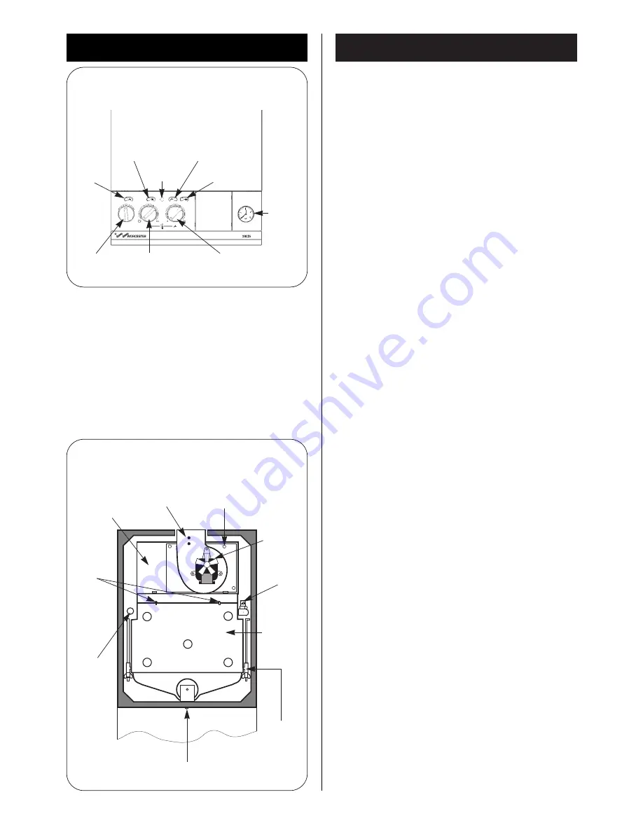
Fig. 27. User controls.
C.H. demand
indicator
D.H.W. demand
indicator
Mains
indicator
Mains
switch
C.H. temp
control
knob
D.H.W.
temp control
knob
System
pressure
gauge
Reset
button
Flame
indicator
Fig. 28. Appliance components and fixings
(upper assembly).
Fan assembly
fixing screws (3)
Sensing tubes
(Red to +)
Flue hood
fixing
screws
Overheat
thermostat
Fan
assembly
Flue hood
Combustion
chamber
fixing bolts
(2)
Burner fixing screw
Combustion
chamber
front and
sides
Central
heating
sensor
+
-
Содержание 28CDi RSF
Страница 23: ...23 109 ...
Страница 24: ...17 Operational Flow Diagrams 24 ...
Страница 25: ...25 ...
Страница 26: ...26 ...
Страница 28: ...28 ...
Страница 29: ...29 ...
Страница 30: ...30 ...
Страница 31: ...31 ...
Страница 32: ...32 ...
Страница 33: ...33 ...
Страница 34: ...34 ...
Страница 35: ...35 ...


