


-9-
Model W1704 (For Machines Mfd. Since 01/20)
SA
FE
T
Y
Additional.Safety.for.Wood.Lathes
INTEGRITY.OF.STOCK.
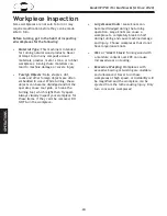
Verify each workpiece is
free of knots, splits, nails, or foreign material
to ensure it can safely rotate on spindle
without breaking apart or causing turning tool
kickback.
WORKPIECE.PREPARATION.
Before mounting, cut
off waste portions with a bandsaw or other
tool to ensure workpiece has no large edges to
catch turning tool, and it will rotate without
dangerous wobbling.
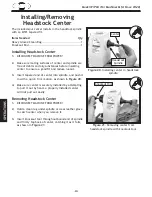
SECURING.LOCKS..
Verify tool rest, headstock,
and tailstock are secure before turning lathe
ON
.
SECURING.WORKPIECE.
An improperly secured
workpiece can fly off spindle with deadly
force. Use proven setup techniques and always
verify workpiece is well-secured before starting
lathe. Only use high-quality fasteners with non-
tapered heads for faceplate attachment.
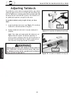
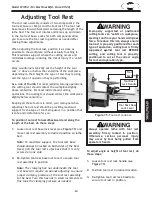
TOOL.SUPPORT.
An improperly supported tool
may be grabbed or ejected. Adjust tool rest
approximately
1
⁄
4
” away from workpiece and
1
⁄
8
” above workpiece center line to provide
proper support for turning tool. Firmly hold
turning tool with both hands against tool rest.
TOOL.KICKBACK.
Occurs when turning tool is
ejected from workpiece with great force,
striking operator or bystanders. Commonly
caused by poor workpiece selection/
preparation, improper tool usage, or improper
machine setup or tool rest adjustment.
ADJUSTMENT.TOOLS..
Remove all chuck keys,
wrenches, and adjustment tools before turning
lathe
ON
. A tool left on the lathe can become
a deadly projectile when spindle is started.
SAFE.CLEARANCES
. Before starting spindle, verify
workpiece has adequate clearance by hand-
rotating it through its entire range of motion.
EYE/FACE.PROTECTION
. Always wear a face
shield and safety glasses when operating lathe.
PROPER.APPAREL.
Do not wear gloves, necktie or
loose clothing. Keep keep long hair away from
rotating spindle.
SPEED.RATES.
Select correct spindle speed for
workpiece size, type, shape, and condition.
Use low speeds when roughing or when turning
large, long, or non-concentric workpieces.
Allow spindle to reach full speed before
turning.
NEW.SETUPS.
Test each new setup by starting
spindle rotation at the lowest speed and
standing to the side of the lathe until
workpiece reaches full speed and you can
verify safe rotation.
ROUGHING.
Use correct tool. Take light cuts, use
low speeds, and firmly support tool with both
hands.
SHARP.TOOLS.
Only use sharp turning tools—
they cut with less resistance than dull tools.
Dull turning tools can catch or grab and pull
your hands into the rotating workpiece.
STOPPING.SPINDLE.
Always allow spindle to
completely stop on its own. Never put hands or
another object on spinning workpiece.
ADJUSTMENTS/MAINTENANCE.
Make sure wood
lathe is turned
OFF
, disconnected from power,
and all moving parts are completely stopped
before doing adjustments or maintenance.
MEASURING.WORKPIECE.
Only measure
workpiece after it has stopped. Trying to
measure a spinning workpiece increases
entanglement risk.
SANDING/POLISHING.
To reduce entanglement
risk, remove tool rest before sanding. Never
completely wrap sandpaper around workpiece.
MAIN.INJURY.HAZARDS:.Death.or.crushing.injury.from.getting.entangled.in.rotating.spindle.or.
workpiece;.death,.blindness,.or.broken.bones.from.being.struck.by.a.workpiece.that.breaks.
apart.or.comes.loose.during.rotation,.turning.tool.kickback,.or.flying.wood.chips..To.minimize.
your.risk.of.these.hazards,.always.heed.the.following.warning.information:
Содержание SHOP FOX W1704
Страница 48: ......