Woods Turf Batwing TBW144 Скачать руководство пользователя страница 71

F-8494 (Rev. 6/23/2005)

©2002 Woods Equipment Company. All rights reserved. WOODS, the Woods logo, and "Tested. Proven. Unbeatable." are trademarks of Woods
Equipment Company. All other trademarks, trade names, or service marks not owned by Woods Equipment Company that appear in this manual are
the property of their respective companies or mark holders. Specifications subject to change without notice. 

WARRANTY

(Replacement Parts For All Models Except Mow’n Machine

TM

Zero-Turn Mowers and Woods Boundary

TM

 Utility Vehicles)

Woods Equipment Company (“WOODS”) warrants this product to be free from defect in material and
workmanship for a period of ninety (90) days from the date of delivery of the product to the original purchaser
with the exception of V-belts, which will be free of defect in material and workmanship for a period of 12 months. 

Under no circumstances will this Warranty apply in the event that the product, in the good faith opinion of
WOODS, has been subjected to improper operation, improper maintenance, misuse, or an accident. This Warranty
does not cover normal wear or tear, or normal maintenance items. 

This Warranty is extended solely to the original purchaser of the product. Should the original purchaser sell or
otherwise transfer this product to a third party, this Warranty does not transfer to the third party purchaser in any
way. There are no third party beneficiaries of this Warranty. 

WOODS’ obligation under this Warranty is limited to, at WOODS’ option, the repair or replacement, free of
charge, of the product if WOODS, in its sole discretion, deems it to be defective or in noncompliance with this
Warranty. 

The product must be returned to WOODS with proof of purchase within thirty (30) days after

such defect or noncompliance is discovered or should have been discovered, routed through the dealer and
distributor from whom the purchase was made, transportation charges prepaid.

 WOODS shall complete

such repair or replacement within a reasonable time after WOODS receives the product.


THERE ARE NO

OTHER REMEDIES UNDER THIS WARRANTY. THE REMEDY OF REPAIR OR REPLACEMENT IS THE
SOLE AND EXCLUSIVE REMEDY UNDER THIS WARRANTY. 

THERE ARE NO WARRANTIES WHICH EXTEND BEYOND THE DESCRIPTION ON THE FACE OF THIS
WARRANTY. WOODS MAKES NO OTHER WARRANTY, EXPRESS OR IMPLIED, AND WOODS
SPECIFICALLY DISCLAIMS ANY IMPLIED WARRANTY OF MERCHANTABILITY AND/OR ANY
IMPLIED WARRANTY OF FITNESS FOR A PARTICULAR PURPOSE.

WOODS shall not be liable for any incidental or consequential losses, damages or expenses, arising directly
or indirectly from the product, whether such claim is based upon breach of contract, breach of warranty,
negligence, strict liability in tort or any other legal theory. 

Without limiting the generality of the foregoing,

Woods specifically disclaims any damages relating to (i) lost profits, business, revenues or goodwill; (ii) loss of
crops; (iii) loss because of delay in harvesting; (iv) any expense or loss incurred for labor, supplies, substitute
machinery or rental; or (v) any other type of damage to property or economic loss.

This Warranty is subject to any existing conditions of supply which may directly affect WOODS’ ability to obtain
materials or manufacture replacement parts. 

No agent, representative, dealer, distributor, service person, salesperson, or employee of any company, including
without limitation, WOODS, its authorized dealers, distributors, and service centers, is authorized to alter, modify,
or enlarge this Warranty. 

Answers to any questions regarding warranty service and locations may be obtained by contacting: 

Содержание Turf Batwing TBW144

Страница 1: ...OPERATOR S MANUAL TURF BATWING MAN0826 Rev 11 15 2013 TBW144 TBW180 TBW204...

Страница 2: ...at www WoodsEquipment com or in the United States and Canada call 1 800 319 6637 The equipment you have purchased has been carefully engineered and manufactured to provide dependable and satisfactory...

Страница 3: ...04 Cutting Width 12 15 17 Cutting Height Range 1 0 5 0 1 0 5 0 1 0 5 0 Shipping Weight Approximately 3 010 lbs 3 300 lbs 3 450 lbs Blade Speed feet per minute 18 000 18 000 18 000 Blade Spindles 7 9 9...

Страница 4: ...ome information may be general in nature due to unknown and varying operating conditions However through experience and these instructions you should be able to develop procedures suitable to your par...

Страница 5: ...ne to approach the equipment Route hydraulic hoses carefully to prevent dam age Hoses must not be twisted bent sharply kinked frayed pinched or come into contact with any moving parts Operate moveable...

Страница 6: ...nted machines is 20 mph 32 km h Regardless of the maximum speed capability of the towing tractor do not exceed the implement s max imum transport speed Doing so could result in Loss of control of the...

Страница 7: ...the terrain during operation Stop power unit and implement immediately upon striking an obstruction Dismount power unit using proper procedure Inspect and repair any damage before resuming operation A...

Страница 8: ...s until engine is stopped power unit is properly secured equip ment and all components are lowered to the ground and system pressure is released by oper ating all valve control levers When lubricating...

Страница 9: ...lean safety decals Avoid spraying too close to decals when using a pressure washer high pressure water can enter through very small scratches or under edges of decals causing them to peel or come off...

Страница 10: ...belt securely fastened Allow no riders RAISED EQUIPMENT CAN DROP AND CRUSH Before working underneath follow all instructions and safety rules in operator s manual and securely block up all corners of...

Страница 11: ...sert pins to lock transport latches n Lower after transport FAILURE TO FOLLOW INSTRUCTIONS CAN RESULT IN SERIOUS INJURY OR DEATH SIDE MOWER TRANSPORT LATCHES 44651 PIN STORAGE POSITION PIN INSERTED TO...

Страница 12: ...ched between tractor and implement Operate tractor controls from tractor seat only Do not stand between tractor and implement when tractor is in gear Make sure parking brake is engaged before going be...

Страница 13: ...unit or attachment Never allow children or untrained persons to operate equipment Keep bystanders away from equipment Make sure spring activated locking pin or collar slides freely and is seated firm...

Страница 14: ...the Constant Velocity CV driveline or damage will occur Check for excessive turn angle 1 Disconnect the driveline from the tractor 2 Start engine and turn as far right or left as possible 3 Shut off t...

Страница 15: ...asuring from mower frame to the ground at each deck rail 2 Verify that the same amount of spacers are under all caster arms 3 Loosen cap screws that attach caster arm assembly to deck 4 Set mower on t...

Страница 16: ...ng proper procedure Inspect and repair any damage before resuming operation Always sit in power unit seat when operating controls or starting engine Securely fasten seat belt place transmission in neu...

Страница 17: ...th during growing seasons Follow local recommendations for the suitable cutting height in your area Operating Tips Inspect and clear area of stones branches or other hard objects that might be thrown...

Страница 18: ...ove ___ Make sure the driveline guards and tether chains are in good condition Guards must rotate freely on driveline Fasten tether chains as instructed to the tractor and the equipment ___ Inspect ar...

Страница 19: ...components are lowered to the ground and system pressure is released by oper ating all valve control levers Before dismounting power unit or performing any service or maintenance follow these steps d...

Страница 20: ...of most guns is sufficient Use SAE 90W gear lube in gearboxes Daily lubrication of PTO slip joints is necessary Failure to maintain proper lubrication can result in damage to U joints gearboxes and o...

Страница 21: ...EQUENCY 1 Caster Wheel Pivots 8 Hours 2 Caster Wheel Hubs 8 Hours 3 Blade Spindles 24 Hours 4 Gearbox Fill 1 2 full with Check For Leaks Daily SAE 90W gear lube 5 Driveline U Joints 8 Hours 6 Wing Piv...

Страница 22: ...y B Route the belt around pulley D as shown 6 Make sure the belt is on drive pulley A route around idler F 7 Grasp the belt between spindle pulley B and spindle pulley D Drive pulley A Pull spring loa...

Страница 23: ...s Careless or improper handling may result in serious injury 1 Remove cap screws 3 lock nut 4 Figure 12 2 Remove blade BLADE SHARPENING NOTICE When sharpening blades be sure to balance them Unbalanced...

Страница 24: ...ay 1 Be careful when spraying near scratched or torn safety decals or near edges of decals as water spray can peel decal off surface 2 Be careful when spraying near chipped or scratched paint as water...

Страница 25: ...ons in swath Conditions too wet for mowing Allow grass to dry before mowing Blades unable to cut that part of grass pressed down by path of tractor tires Slow ground speed of tractor but keep engine r...

Страница 26: ...rs Check belt for free travel in pulleys Check under mower and around blade spindle shaft for wire rags or other foreign material Clean all material from under mower Frayed edges on belt cover Belt mi...

Страница 27: ...VICE Spindle Repair Spindle repair requires special skills and tools If your shop is not properly equipped or your mechanics are not trained in this type of repair you may be time and money ahead to u...

Страница 28: ...g cone into spindle with taper positioned to mate with cup 4 Identify the open side of the seal containing the spring 5 Apply a thin coat of Permatex to the area of housing where seals seat 6 Install...

Страница 29: ...ARBOX SERVICE Gearbox Removal from Mower Figure 17 1 Disconnect and remove the rear driveline from the gearbox 2 Remove vent plug and siphon gear lube from housing through this opening 3 Remove gearbo...

Страница 30: ...ll will bow seal cage and ruin seal 5 Carefully press seal into housing avoiding distortion to the metal seal cage Figure 18 Seal Installation Figure 19 Gearbox Assembly Vertical Shaft Repair Figure 1...

Страница 31: ...a punch and hammer from the top outside the housing 15 Support housing upside down top cover surface and remove bearing 6 by using a punch and hammer from the bottom side of the housing 16 Inspect ge...

Страница 32: ...r 90W EP oil until it runs out of side level hole Tighten all plugs Gearbox Installation NOTE Gearbox is heavy do not attempt to move with out mechanical assistance 1 Set gearbox on gearbox stand and...

Страница 33: ...l cross into bearing cup with grease fitting away from shaft Be careful not to disturb needle bearings Insert another bearing cup directly across from first cup and press in as far as possible with ha...

Страница 34: ...ove Always wear relatively tight and belted clothing to avoid getting caught in moving parts Wear sturdy rough soled work shoes and protective equipment for eyes hair hands hearing and head and respir...

Страница 35: ...e tubes using blanks 4 3 8 bolts 6 and nuts 7 4 Secure left and right lamp 1 2 to brackets using 1 4 bolts 8 and nuts 9 5 Connect light to wiring harness 6 Pull any slack out of main wire and install...

Страница 36: ...nge Lock Nut 3 1 2 NC x 9 HHCS GR5 4 Flat Washer 1 2 SAE 5 Carriage Bolt 3 8 NC x 1 6 Flanged Whiz Nut 3 8 NC 7 Spacer 75 x 6 62 8 Bracket Front Roller 9 Roller 4 x 7 37 10 Bearing Roller Kit Front Co...

Страница 37: ...ed 3 Attach item 2 to wing release lever using items 10 and 11 4 Attach base end of cylinder 3 to item 1 using items 7 8 and 9 Cylinder ports should be pointing upward 5 Attach rod end of cylinder 3 t...

Страница 38: ...ding 3 Wear safety glasses or goggles to prevent eye injury while drilling holes 4 Clamp mulching kit in place Make sure baffles are completely closed off by the kit 5 Inspect fit up to confirm that t...

Страница 39: ...Assembly 39 MAN0826 8 31 2010 NOTES...

Страница 40: ...lar slides freely and is seated in groove on tractor PTO shaft ___ Show customer how to determine the turning lim its of the CV PTO driveline ___ Show customer the safe proper procedures to be used wh...

Страница 41: ...LY 53 TBW144 REAR DECK TBW180 TBW204 FRONT ROLLER ASSEMBLY OPTIONAL 54 TBW144 WING DECK FRONT ROLLER ASSEMBLY OPTIONAL 54 REAR ROLLER ASSEMBLY OPTIONAL 55 REAR CHAIN SHIELDING ASSEMBLY 55 REAR WING DR...

Страница 42: ...42 Parts MAN0826 8 31 2010 TBW144 TBW180 TBW204 MAIN FRAME ASSEMBLY Rev 11 15 2013...

Страница 43: ...Bracket 19 24611 1 SMV Emblem 20 38296 1 Rope 25 x 95 0 21 38295 3 Rope clamp 22 38257 3 S Hook 25 x 2 25 REF PART QTY DESCRIPTION 23 38294 1 Rope 25 x 46 0 24 1031166 2 Hydraulic cylinder 3 x 10 see...

Страница 44: ...44 Parts MAN0826 8 31 2010 TBW144 TBW180 TBW204 TRAILER ASSEMBLY Rev 11 15 2013...

Страница 45: ...el Tire 20 5 x 8 00 x 10 Gray 38475 Wheel Rim 5 Bolt 8 00 x 10 Gray 29 3443 1 Hydraulic hose holder 30 1031776 1 Wing stop mount bracket 31 1031780 1 Wing stop TBW144 or 31 1038403 1 Rear wing stop TB...

Страница 46: ...888 Trunnion rear deck 6 1 1026530 1026530 1026530 Manual tube 7 2 71444 71444 71444 Rubber bumper 8 2 38264 38264 38264 Pin lynch chain cotter 9 2 58980 58980 58980 Pin wing deck link 10 4 58982 5898...

Страница 47: ...med 10 64555 1 Idler Flat 5 5 Dia 11 58989 1 Idler Arm Assembly 12 53595 1 Idler Flat 5 0 Dia 13 67131 1 Spring Ext 177 x 1 22 x 9 88 14 35193 2 Bearing Ball REF PART QTY DESCRIPTION 15 1002048 1 Clut...

Страница 48: ...Idler Flat 5 0 Dia 13 67131 1 Spring Ext 177 x 1 22 x 9 88 14 35193 2 Bearing Ball 15 1002048 1 Clutch Shield REF PART QTY DESCRIPTION 16 35141 2 Ring Retaining Int 062 x 1 56 20 1266 Pin Cotter 3 16...

Страница 49: ...7 52855 2 Sleeve 1 28 x 1 66 x 1 00 8 52854 2 Sleeve 1 28 x 1 66 x 75 9 52853 1 Sleeve 1 28 x 1 66 x 50 10 7163 1 Washer Flat 1 1 4 Standard REF PART QTY DESCRIPTION 1 1001020 1 Wheel Hub Axle Assemb...

Страница 50: ...50 Parts MAN0826 8 31 2010 CASTER ARM WHEEL ASSEMBLY...

Страница 51: ...24 11900 1 2 NC Flange lock nut 25 12296 1 4 28 Grease fitting HHCS Hex Head Cap Screw Standard Hardware obtain locally REF PART QTY DESCRIPTION 1 WP1031703G 1 Wheel Gray 18 00 x 9 50 x 8 1031819 Whe...

Страница 52: ...er B4 x 50 10 57466 2 Snap Ring 11 57467 1 Snap Ring 12 57373 1 Spacer 35 5 x 48 x 2 5 13 57328 2 Kit Shim 60 3 x 71 6 14 57468 1 Nut Castle 15 51946 1 Nut Castle M24 x 2 16 57328 1 Kit Shim 30 3 x 44...

Страница 53: ...t TBW180 Complete 9 blades 16 9204BDKT Blade Kit High Lift TBW204 Complete 9 blades 16 7144BDKT2 Blade Kit Low Lift TBW144 Complete 7 blades 16 9180BDKT2 Blade Kit Low Lift TBW180 Complete 9 blades 16...

Страница 54: ...1006420 1 Spacer 75 x 6 62 8 1006419 1 Bracket front roller 9 1006418 1 Roller 4 x 7 37 10 35193 2 Bearing Standard Hardware Obtain Locally REF PART QTY DESCRIPTION 1006421 Roller Kit Front Complete...

Страница 55: ...54 for 5 ft 66 for 6 ft REF PART QTY DESCRIPTION 3 55345 1 Shield Chain Plate or 3 53554 1 Shield Chain Plate or 3 58997 1 Shield Chain Plate 14 6697 Bolt Carriage 3 8 NC x 1 15 14350 Nut Flanged Lock...

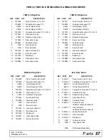
Страница 56: ...56 Parts MAN0826 8 31 2010 TBW144 TBW180 TBW204 REAR WING DECK DRIVES...

Страница 57: ...001305 1 Flexible pin 14 1026988 1 Outer yoke tube 15 1026989 1 Inner yoke tube TBW204 Wing Drive Rear Deck Drives REF PART QTY DESCRIPTION A 1023228 Drive Cmpl 40 28 3 x 46 4 1 1026999 1 Complete col...

Страница 58: ...it 35CV 4 52522 1 CV Body w fitting 5 1021321 1 Yoke and shaft CV splined 20 9 6 1024636 2 Drive shaft bearing kit REF PART QTY DESCRIPTION 7 18864 1 Decal danger rotating driveline 8 1021302 1 Outer...

Страница 59: ...4 35E 4 1032291 1 CAT 4 CV Body w fitting 5 1034255 1 Yoke and shaft CV splined 20 7 6 1024636 2 Drive shaft bearing kit REF PART QTY DESCRIPTION 7 18864 1 Decal danger rotating driveline 8 1021302 1...

Страница 60: ...yoke 2 36990 1 U Joint repair kit 3 1011756 1 Yoke outer 4 1001330 1 Flexible pin 5 1028776 1 Outer bearing ring REF PART QTY DESCRIPTION 6 30922 6 Retainer shield 7 1011757 1 Centering ring 8 1011755...

Страница 61: ...A 2G 2A 1 Wiper seal 2B 1 Rod seal 2C 1 Rod O ring 2D 2 Cap seal 2E 2 Cap O ring 2F 2 Piston seal 2G 1 Piston O ring 3 N S N S 1 Cylinder housing rod end 4 N S N S 1 Piston 5 N S N S 1 Jam nut 6 N S N...

Страница 62: ...ght 4 pin left 3 1031386 2 Light bracket 4 1031388 2 Blank 16 x 4 00 x 4 00 5 1004479 1 Wire harness 6 31138 3 8 NC x 3 1 2 HHCS GR5 7 14350 3 8 NC Flange lock nut 8 10378 1 4 NC x 1 Hex head cap scre...

Страница 63: ...dware obtain locally INSTALLATION INSTRUCTION 1 Locate and drill three 17 32 holes using the dimensions from the drawing and table above 2 Secure skid shoe with three cap screws 3 and flange washers 4...

Страница 64: ...ON 1004116 Anti Streaking kit TBW 1 1004117 4 Anti Streaking bracket 2 14350 3 8 NC Flange lock nut 3 839 3 8 NC x 1 Hex head cap screws GR5 Standard hardware obtain locally INSTALLATION INSTRUCTION 1...

Страница 65: ...proceeding 3 Wear safety glasses or goggles to prevent eye injury while drilling holes 4 Clamp mulching kit in place Make sure baffles are completely closed off by the kit 5 Inspect fit up to confirm...

Страница 66: ...ng upward 5 Attach rod end of cylinder 3 to item 2 using items 7 8 and 9 6 Install reducers 4 elbows 5 and hoses to base of cylinder REF PART QTY DESCRIPTION 1032454 TBW Hydraulic Latch Release Kit 1...

Страница 67: ...1 2 467 634 722 979 1020 1383 Diameter Thread Pitch Millimeters Wrench Size COARSE THREAD FINE THREAD Diameter Thread Pitch Millimeters MARKING ON HEAD MARKING ON HEAD Metric 8 8 Metric 10 9 Metric 8...

Страница 68: ...HHCS Hex Head Cap Screw HT Heat Treated JIC Joint Industry Council 37 Degree Flare LH Left Hand LT Left m Meter mm Millimeter M Male MPa Mega Pascal N Newton NC National Coarse NF National Fine NPSM...

Страница 69: ...nty Product 70 Replacement Parts 71 Operation Adjustment Cutting Height Chart 15 Attaching Mower to Tractor 13 Attaching Hydraulic Hoses 14 Check List Pre Operation Owners Responsibility 18 Cutting He...

Страница 70: ...overed routed through the dealer and distributor from whom the purchase was made transportation charges prepaid WOODS shall complete such repair or replacement within a reasonable time after WOODS rec...

Страница 71: ...of of purchase within thirty 30 days after such defect or noncompliance is discovered or should have been discovered routed through the dealer and distributor from whom the purchase was made transport...

Страница 72: ...1 Woods Equipment Company All rights reserved WOODS the Woods logo and Tested Proven Unbeatable are trademarks of Woods Equipment Company All other trademarks trade names or service marks not owned by...

Отзывы: