


28
Dealer Service
MAN0826 (8/31/2010)
Spindle Disassembly
1.
Place spindle assembly in press and press shaft
down through housing.
2.
Remove seals from housing.
3.
Remove bearing cups from housing by placing a
punch in the slots provided and driving them out.
Alternate punch positions from side to side. Take
care to prevent housing damage.
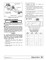
Spindle Assembly
(Figure 15 & Figure 16)
NOTICE
■
Improper positioning of seals can cause seal
damage. An improperly installed seal will leak and
could cause bearing failure.
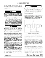
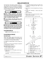
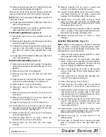
Figure 15
. Spindle and Shaft Assembly
Bearing cones and cups are designed to work together.
It is important to position them so bearing cone taper
mates with cup taper.
1.
Lubricate new cups with a light oil. Place them in
spindle housing so they will mate with bearing
cones. Cups and cones are a press fit to minimize
wear.
2.
Seat cups securely with a press or place a large
drift in the flat lip and drive them into housing until
cup seats against machined shoulder of housing.
3.
Place bottom bearing cone into spindle with taper
positioned to mate with cup.
4.
Identify the open side of the seal containing the
spring.
5.
Apply a thin coat of Permatex to the area of
housing where seals seat.
6.
Install bottom seal with spring up toward center of
housing.
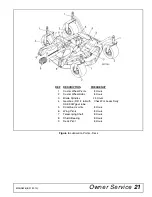
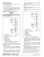
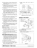
Figure 16
. Spindle and Shaft Assembly
7.
Place seal squarely on housing and select a piece
of pipe or tubing with an OD that will set on outside
edge of seal. A tubing with an OD that is too small
will bow seal cage.
8.
Carefully press seal into housing to prevent
distortion to metal seal cage. Bottom seal should
seat firmly and squarely against machined
shoulder in housing.
9.
Make sure seal lip did not roll under. Distortion to
seal cage or damage to seal lip will cause seal to
leak. Damaged seals must be replaced.
10.
Insert shaft and bearing through bottom of housing.
11.
Fill housing cavity with a medium grade grease.
12.
Install top bearing on shaft to mate with top cone.
1. Grease fitting
2. Seal, 1.50 x 2.12 x .31
3. Sleeve, 1.14 x 1.50 x .55
4. Bearing cone
5. Bearing cup
6. Spindle housing
7. Shaft, blade spindle
1. Grease fitting
2. Seal, 1.50 x 2.12 x .31
3. Sleeve, 1.14 x 1.50 x .55
4. Bearing cone
5. Bearing cup
6. Spindle housing
7. Shaft, blade spindle
Содержание Turf Batwing TBW144
Страница 1: ...OPERATOR S MANUAL TURF BATWING MAN0826 Rev 11 15 2013 TBW144 TBW180 TBW204...
Страница 39: ...Assembly 39 MAN0826 8 31 2010 NOTES...
Страница 42: ...42 Parts MAN0826 8 31 2010 TBW144 TBW180 TBW204 MAIN FRAME ASSEMBLY Rev 11 15 2013...
Страница 44: ...44 Parts MAN0826 8 31 2010 TBW144 TBW180 TBW204 TRAILER ASSEMBLY Rev 11 15 2013...
Страница 50: ...50 Parts MAN0826 8 31 2010 CASTER ARM WHEEL ASSEMBLY...
Страница 56: ...56 Parts MAN0826 8 31 2010 TBW144 TBW180 TBW204 REAR WING DECK DRIVES...


