


Owner Service
25
MAN0826 (8/31/2010)
TROUBLESHOOTING
MOWING CONDITIONS
PROBLEM
POSSIBLE CAUSE
SOLUTION
Grass cut higher in center of
swath than at edge
Height of mower higher at front
than at rear
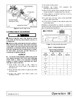
Adjust mower height and attitude so that
mower rear and front are within 1/2 inch
of same height. See instructions on
page 15.
Loose Blade
Check blade hardware.
Grass cut lower in center of
swath than at edge
Height of mower lower at front
than at rear
Adjust mower height and attitude so that
mower rear and front are within 1/2 inch
of same height. See instructions on
page 15.
Loose Blade
Check blade hardware.
Streaking conditions in swath
Conditions too wet for mowing
Allow grass to dry before mowing.
Blades unable to cut that part of
grass pressed down by path of
tractor tires
Slow ground speed of tractor but keep
engine running at full PTO rpm.
Cutting lower will help.
Adjust tractor tire spacing if possible.
Dull blades
Sharpen or replace blades.
Loose Blade
Check blade hardware.
Material discharges from mower
unevenly; bunches of material
along swath
Material too high and too much
material
Reduce ground speed but maintain 540
rpm at tractor PTO, or make two passes
over material.
Raise mower for the first pass and lower
for the second and cut 90 degrees to first
pass.
Raise rear of mower high enough to
permit material discharge.
Grass wet
Allow grass to dry before mowing. Slow
ground speed of tractor but keep engine
running at full PTO rpm.
Содержание Turf Batwing TBW144
Страница 1: ...OPERATOR S MANUAL TURF BATWING MAN0826 Rev 11 15 2013 TBW144 TBW180 TBW204...
Страница 39: ...Assembly 39 MAN0826 8 31 2010 NOTES...
Страница 42: ...42 Parts MAN0826 8 31 2010 TBW144 TBW180 TBW204 MAIN FRAME ASSEMBLY Rev 11 15 2013...
Страница 44: ...44 Parts MAN0826 8 31 2010 TBW144 TBW180 TBW204 TRAILER ASSEMBLY Rev 11 15 2013...
Страница 50: ...50 Parts MAN0826 8 31 2010 CASTER ARM WHEEL ASSEMBLY...
Страница 56: ...56 Parts MAN0826 8 31 2010 TBW144 TBW180 TBW204 REAR WING DECK DRIVES...


