22
Owner Service
MAN1281 (4/15/2019)
Seasonal Lubrication
In addition to the daily recommended lubrication, a
more extensive application is recommended season-
ally.
1.
Fill CV double yokes with 20 pumps of grease with
the joints in a straight line.
2.
Articulate CV body to maximum angle several
times to ensure full coverage of joints.
3.
Place joints in the straight position and add 10
additional pumps of grease to both joints.
4.
Wipe telescoping drive clean of all old grease and
contaminants.
5.
Add a thin layer of new grease over telescoping
drive.
BLADES
Your dealer can supply genuine replacement
blades. Substitute blades may not meet original
equipment specifications and may be dangerous.
Before working underneath, read manual
instructions, securely block up, and check stability.
Secure blocking prevents equipment from drop-
ping due to hydraulic leak down, hydraulic system
failure, or mechanical component failure.
Blade Removal
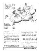
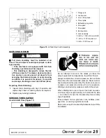
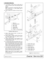
(Figure 7)
Figure 7
. Blade Assembly
1.
Disconnect driveline from tractor PTO.
2.
Raise cutter and block securely (see Figure 6).
3.
Align crossbar (8) with blade access hole in the
cutter frame. Remove cap screw (50), blade pin
lock clip (12, keyhole plate (11), and shims (9 &
10). Carefully drive blade pin (7) out of crossbar.
4.
Rotate crossbar and repeat for opposite blade.
NOTICE
■
If blade pin (7) is seized in crossbar and extreme
force will be needed to remove it, support crossbar
from below to prevent gearbox damage.
Blade Installation
(Figure 7)
Service and maintenance work not covered in
OWNER SERVICE must be done by a qualified
dealership. Special skills, tools, and safety proce-
dures may be required. Failure to follow these
instructions can result in serious injury or death.
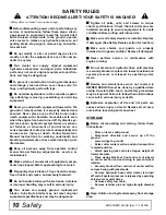
Before servicing, adjusting, repairing, or unplug-
ging, stop tractor engine, place all controls in neu-
tral, set park brake, remove ignition key, and wait
for all moving parts to stop.
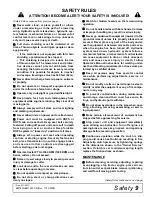
Never perform cleaning, service, or maintenance
with engine running.
Keep all persons away from operator control
area while performing adjustments, service, or
maintenance.
Before working underneath, disconnect driveline
from tractor, lower wings to ground, raise cutter,
and pin transport bar in raised position. Attach
parking jack and lower to ground. Securely block
all four corners of center section and each wing
with jack stands. Blocking up prevents the cutter
from dropping due to hydraulic leak down, hydrau-
lic system failure, or mechanical component fail-
ure.
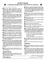
If you do not understand any part of this manual
and need assistance, see your dealer.
Always wear relatively tight and belted clothing
to avoid entanglement in moving parts. Wear
sturdy, rough-soled work shoes and protective
equipment for eyes, hair, hands, hearing, and head.
Wear a respirator or filter mask where appropriate.
NOTICE
■
Crossbar rotation has clockwise rotation on left
gearbox and counterclockwise rotation on the right
and center gearboxes when looking down on cut-
ter. Be sure to install blade cutting edge to lead in
correct rotation.
NOTE:
Always replace or sharpen both blades at the
same time.
WARNING
WARNING
7. Blade pin
8. Crossbar assembly
9. Shim, 18 GA
10. Shim, 20 GA
11. Keyhole plate
12. Blade lock clip
50. 1/2 NC x 1-1/4 HHCS GR5
WARNING
WARNING
Содержание BATWING BW13.70
Страница 55: ...Common Components 55 MAN1281 4 15 2019 NOTES...
Страница 56: ...56 50 Series Parts MAN1281 4 15 2019 CENTER FRAME ASSEMBLY BW20 50 BW20 50Q...
Страница 60: ...60 50 Series Parts MAN1281 4 15 2019 WING CENTER GEARBOX ASSEMBLY BW20 50 BW20 50Q...
Страница 65: ...50 Series Parts 65 MAN1281 4 15 2019 NOTES...
Страница 66: ...66 60 Series Parts MAN1281 4 15 2019 CENTER FRAME ASSEMBLY BW20 60 BW20 60Q...
Страница 70: ...70 60 Series Parts MAN1281 4 15 2019 WING CENTER GEARBOX ASSEMBLY BW20 60 BW20 60Q...
Страница 76: ...76 70 Series Parts MAN1281 4 15 2019 CENTER FRAME ASSEMBLY BW20 70 BW20 70Q BW13 70 BW13 70Q BW13 70QREV...
Страница 80: ...80 70 Series Parts MAN1281 4 15 2019 WING CENTER GEARBOX ASSEMBLY BW20 70 BW20 70Q BW13 70 BW13 70Q BW13 70QREV...

