background image


12 


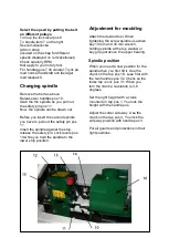
Select the speed by putting the belt 
on different pulleys. 

Turn up the lock lever pos 8 
To handle item 7 on the right 
See remväxellucka 
Add on strap. 
(located on the strap for different 
speeds displayed on remväxelhuset) 
Check carefully RPM 
that apply to your rotary tool. 
För handtag pos 7 till vänster. Tryck på 
med normal handkraft och lås läget 
med låsspak 8. 
 

Changing spindle 

 
Remove the belt as above 
Release two handles pos 10. 
Grab the the spindle as you pull out 
the safety pin pos 11 
Now, the spindle can be drawn out. 
 
Before you insert the second spindle 
you have to pull out the safety pin pos 
11 
Insert the spindle against the stop, 
release the safety pin. Lock levers pos 
10 while you hold the spindle to the 
lower stop position. 


Adjustment for moulding


Attach the desired tool. When 
tightening the screw spindle use Allen 
key 10 mm and 30 mm wrench, 
holding spindle at the top washer or 
key grip just above the upper bearing. 
 

Spindle position  


When you need a new position for the  
spindle then you first tilt it. Use the 
crank on the tap pos 18. Lose first with 
the two handles pos 32. Check so the 
index tap is out, pos 31. When you 
turn the crank a revolution is 3,6 
degrees.  


Set the right height with a crank 
mounted on tap pos 1. You lock the 
height with the handle pos.  


Adjust the cutter side way. Use the 
crank on the tap pos 4. You lock the 
side way position with handle pos 3.  


Put all guards and protections in their 
right positions.  


Содержание PH365

Страница 1: ...re the machine is used LIFTING MACHINE using forklift or pallet truck When replacing parts use only genuine parts and note that all electric must be installed by a professional Floor space The machine needs a space on 2 m width The length depending on how long working pieces are Min length is 5 m Anchoring For maximum safety the machine anchored to the floor with screws Dia 8 10 mm Application The...

Страница 2: ... such services etc must be the main circuit breaker pos a9 be in OFF position Check that the lamp pos a10 is off The bottom black button bar starts planer engines pos a8 The upper red button bar stopped planed engines pos a7 Above each key is a lamp pos a6 indicating that each motor will go Button functions as the right 1 Start by cutter lower horizontal cutter 2 Start of Side cutter right 3 Start...

Страница 3: ...ter Cutters used must comply with EN 847 1 Table Surfaces The tables are molded with the highest quality Table surfaces are specially processed to obtain the highest precision and good sliding properties When the machine is new a break in period until the tables get a slightly shinier surface to maintain optimum sliding properties Tools Required List of necessary tools to work with the machine 4 m...

Страница 4: ...or hands in the input or outfeed part during operation Do not interfere with the machine before you ensure that the machine is no power and can not be started accidentally Planing Measure the work piece and set the appropriate thickness and width before planing Accident risk is great if you enter a piece that has the small height not to feed rollers can not reach into the work piece Small dimensio...

Страница 5: ...ont desk item 212 4 Fit the rear table item 253 5 Connect the machine to chip extractor 6 Before the machine is connected to the network verify that all cutters can rotate freely and that all parts are fixed 5 Connect the electrical machine Watch out for rotation Before starting Make sure all the cutters can rotate freely Make sure the emergency stop a11 is pulled out Make sure the top cover is cl...

Страница 6: ...n planed Chip thickness up to 8 mm Knives under and upper cutter When the blades has lost its sharpness whetstone them When the edge has injuries or is not straight knives must be grinded Always sharpen knives in pairs so that the knives has the same width otherwise vibrations occurs in the cutter Angle of 40 degrees Before reinstalling and setting the knives and wedges you must clean them careful...

Страница 7: ...es are pressed by the wedges Profile Steel in horizontal cutters Profile knives can be fitted in the cutters Profile knives must always be installed in pairs in the same lateral position opposite each other If the profile steel cutters can be mounted in a protrusion Under cutter Profile depth of more than 10 mm shall be placed so that they fit in the slots in the table Installation and setup of pr...

Страница 8: ...cal cutters No 2 and 3 Spiders on the side cutters are 30 mm in diameter which is a standard Thus there is a wide selection of cutters available At delivery the machine is equipped with two cutter heads in which you can mount the molding knives or straight steel The top nut on the movable cutter has a left winding Disassembly Loosen the nut is 7 11 with a 30 mm wrench and a wrench Unscrew the nut ...

Страница 9: ... With the shim rings you can then adjust the height as desired Adjusting the fence at vertical cutter right No 2 The front fence pos 220 controls how much the cutter to harvest Normally you let the fixed cutter take 2 mm Felling adjusted with lever pos 216 and locked with lever pos 223 Rear fence Rear fence pos 34 is fixed with 6 mm screws on the mounting blocks in its angular position Fences with...

Страница 10: ...e indicator The indicator shows the width dimension in mm black and 1 10 mm red At each shift to the new profile planing a board measure the outer dimension of caliper Turn the small knob on the right indicator so this measurement is shown in the window Then set the correct dimensions Adjust the arm pos 77 with side rollers so that the board will be printed in police custody Set up roller item 76 ...

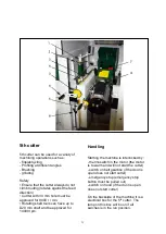
Страница 11: ... tools can have up to D20 mm shaft and be approved for 14000 rpm Handling Starting the machine is interlocked by thermoswitch in the motor the motor is to warm and will not start the cutter switch on belt gearbox if the door is open does not start cutter emergency stop emergency stop button must be pulled out switch on hood if the door is open does not start cutter On the backside of the machine i...

Страница 12: ...indle against the stop release the safety pin Lock levers pos 10 while you hold the spindle to the lower stop position Adjustment for moulding Attach the desired tool When tightening the screw spindle use Allen key 10 mm and 30 mm wrench holding spindle at the top washer or key grip just above the upper bearing Spindle position When you need a new position for the spindle then you first tilt it Us...

Страница 13: ...ake the adjustments Run a test board and stop the machine when it is inside the machine Now you see how well the machine works Adjusting the fence can also easily be made Then measure the profile height and width Adjust ...

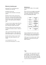
Страница 14: ...o that you can come back to the perfect speed for your needs 0 on the clock is 3 m min 8 of the clock becomes 15 m min Maintenance Oil should be visible in the oil sight glass Fill on oil if it is not visible in the glass Use oil for automatic transmissions according to the table or with the oil that is compatible with these AGIP BLASIA 32 SHELL A T F DEXRON ESSO A T F DEXRON MOBIL A T F 220 CASTR...

Страница 15: ...s not power connected before any maintenance After each session Clean the machine from the chips Clean the table from the resin Apply table with paraffin oil Maintenance at regular intervals the following Lubricate the following parts with oil on a regular basis The feed rollers bearings Elevator spindles and its upper and lower bearings The chain thats adjust the table height The chain for drivin...

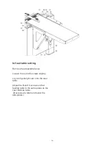
Страница 16: ...e adjustable fence Loosen the A and D screws slightly Lay a long straight ruler onto the cast table Adjust the B and C screws so that feeding table in the same plane as the cast machine table B screws are Allen and below the side plates ...

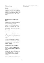
Страница 17: ...utter is lifted slightly 5 Lock bolts to the frame Adjusting the table to the cutter for example the chain is loose or too little adjustment range is left for the cutter 1 Place an absolutely flat block on the table in the middle of the cutter 2 Crank flat table so that the block touches the cutter 3 Remove the chain to the table 4 Turn up every spindle so that the cutter touches the block for its...

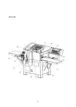
Страница 18: ...18 Overview ...

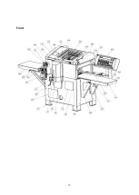
Страница 19: ...19 Front ...

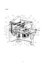
Страница 20: ...20 Front ...

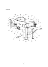
Страница 21: ...21 Backside ...

Страница 22: ...22 Backside ...

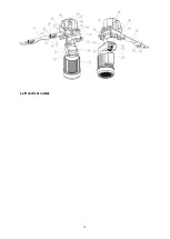
Страница 23: ...23 Left vertical cutter ...

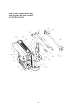
Страница 24: ...24 Under cutter right vertical cutter slide ways for left vertical cutter lock device for table ...

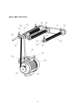
Страница 25: ...25 Upper cutter feed rollers ...

Страница 26: ...ufacturers MOReTENs AB M10 Nifsåsvägen 11 831 52 ÖSTERSUND hereby certify that Foursided moulder MOReTENs PH360 No 360 000 meet the standard of 2006 42 EC Further declared the following parts of harmonized standards have been met A 861 Östersund 2016 Bo Mårtensson MD ...

Отзывы: