
-17-
- Remove rear door of the jointer stand.
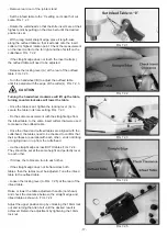
- Set the infeed table to the ‘0’ setting on its depth of cut
scale. FIG. 7.2.1.
- Rotate the cutterhead so that the knife inserts are at their
highest point by pulling on the drive belt until the desired
position is set.
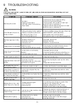
- With a long metal straight edge, place it length-wise
along the outfeed table so that it extends onto the insert
cutter at its highest rotation point. Check the measurement
on the insert cutter to the far right and then far left on the
cutterhead. FIG. 7.2.2.
- If the straight edge does not touch the insert cutter(s),
the outfeed table will need to be adjusted.
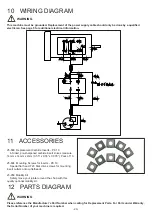
- Release the locking lever (A) at the rear of the outfeed
table. FIG. 7.2.3.
- Turn the handwheel (B) to adjust the outfeed table
until it is parallel with the edge of the cutter(s). FIG. 7.2.3.
Turning the handwheel clockwise will lift up the table,
turning counterclockwise will lower the table.
- Once the table is set, tighten the locking lever (A) to
secure the table in its new setting. FIG. 7.2.3.
- Do the same measurement with the straight edge from
the infeed table, to the same insert cutters that were used
to measure the outfeed table.
- Once the infeed and outfeed tables are aligned with the
cutterhead, the tables need to be checked to confirm that
their surfaces are parallel with each other - ends not tilting
or angling down or up from the cutterhead.
- Lie the straight edge across BOTH tables. FIG. 7.2.4.
They should be set at the same height and perfectly level
to each other.
- If it does, the tables are true to each other.
- If the straight edge does not lie flat across both
tables, then the tables must be adjusted. Tune the infeed
table to the outfeed table.
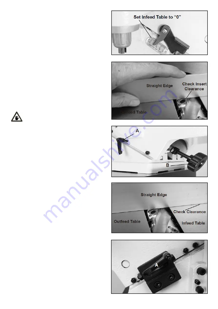
- Loosen the locking lever (A-FIG. 7.2.5) at the rear of the
infeed table.
Raise or lower the table adjustment handle (not shown)
and check the clearance between the straight edge and
infeed table as shown in FIG. 7.2.4.
Adjust the upper positive stop by unlocking the 10mm lock
nut and turning the Allen bolt until the desired result is
achieved. Retain the adjustment by tightening the 10mm
lock nut.
FIG.7.2.1
FIG.7.2.2
FIG.7.2.3
FIG.7.2.4
FIG.7.2.5
CAUTION