background image

-18-

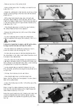
7.3   CHANGING THE DRIVE BELT

- Remove rear stand panel door.

- Loosen the the four 13mm mounting bolts and nuts on 

the outer slide rail.

- Thread the drive belt through the opening in the stand 

and hang it on the spindle pulley.

- Lift up the motor and center the drive belt on the motor 

pulley. Fig. 7.3.1.

- Allow the weight of the motor to determine the proper 

belt tension. The drive belt should be set between 3/8” and 

1/2” deflection when side pressure is applied. Fig. 7.3.2.

- Tighten the the four 13mm mounting bolts and nuts on 

the outer slide rail.

- Install rear stand panel door.

FIG.7.3.1

FIG.7.3.2

8   MAINTENANCE

Turn the power switch “OFF” and disconnect the plug from the outlet prior to adjusting or maintaining the 

machine. DO NOT attempt to repair or maintain the electrical components of the motor. Contact a qualified 

service technician for this type of maintenance.

- Before each use:

  - Check the power cord and plug for any wear or damage.

  - Check for any loose screws or hardware.

  - Check the area to make sure it is clear of any misplaced tools, lumber, cleaning supplies, etc. that could hamper the 

safe operation of the jointer.

- To avoid a build-up of wood dust, regularly clean all parts of the machine using a soft cloth, brush or compressed air. A 

general cleaning should be done after every use to avoid future problems and ensure the machine is in ready condition 

for the next time it is used.

If blowing sawdust, wear proper eye protection to prevent debris from blowing into eyes. Air pressure above 50 

PSI should not be used as high-pressured air may damage insulation, etc.

- Check the knife inserts to make sure that they are not loose from the cutterhead, dull or nicked. Making sure that they 

are in proper operating condition will ensure that the quality of your surfaced lumber will be the best possible.

- Lubricate all bearing points regularly with a few drops of light motor oil. Cutterhead ball bearings are lifetime lubricated, 

sealed, and do not need any fur-ther care. Keep the drive belt free of oil and grease.

- Keep the jointer tables free of resin and rust. Clean them regularly with a non-flammable solvent, then coat with a light 

film of dry lubricant spray, or wax, to enhance passage of work piece on/over the tables. Never use solvents to clean 

plastic parts, as they could dissolve or damage the material.

When cleaning or working on the tables, avoid the risk of personal injury by cuts that may result from touching 

the knife inserts’ sharp edges! 

- Check the drive belt tension after the first 3-5 hrs. of operation to ensure that the belts have not become stretched and 

loose from their ‘breaking in’ use. See page 19 for instructions.

WARNING

CAUTION

CAUTION

Содержание PL200A

Страница 1: ...MMONPLACE LWAYS REMEMBER THAT A CARELESS FRACTION OF A SECOND IS SUFlCIENT TO INmICT SEVERE INJURY LWAYS WEAR SAFETY GLASSES WHEN USING WOODWORKING EQUIPMENT LWAYS READ THE INSTRUCTIONS PROVIDED BEFORE USING WOODWORKING EQUIPMENT Wood Planer PL200A Version V 1 201810 6ERSION EBRUARY 7OODWORKING ACHINES CCESSORIES 4ELEPHONE AX 3TARTRITE 5NIT DELPHI 7AY 3TAVELEY 3 3 MAIL SALES RECORDPOWER CO UK WWW ...

Страница 2: ...ACHINE 5 2 DRIVE BELT INSTALLATION 5 3 DRIVE BELT PULLEY ALIGNMENT 5 4 INSTALLING THE FENCE 5 5 DUST PORT ASSEMBLY 5 6 INSTALLING THE CUTTERHEAD GUARD 5 7 INSTALLING THE INFEED TABLE LEVER 5 8 OUTFEED TABLE ADJUSMENT KNOB 5 9 SWITCH POST INSTALLATION 6 OPERATION 6 1 STARTING AND STOPPING JOINTER 6 2 DIRECTION OF GRAIN 6 3 JOINTER OPERATION 6 4 FEEDING THE WORKPIECE 6 5 SETTING DEPTH OF CUT 6 6 FEN...

Страница 3: ...ersonnel and machine profitable work as well as long life of the machine itself For better clarity this manual is divided in separate parts in which are contained the more important subjects The contents will allow you to find fast the specific subjects The important text is printed in bold and is marked by the following symbols 1 2 MACHINE IDENTIFICATION There is a identification plate fixed to t...

Страница 4: ...ke sure the machine will not being operated wrongly After an initial bedding in period or many hours of operation the driving belts may slacken this causes an increase in the tool stopping time Immediately tighten them The working area around the machine must be kept always clean and clear in order to have an immediate and easy access to the switchboard Never insert materials which are different f...

Страница 5: ... protection masks Never let unauthorized people repair service or operate the machine The manufacturer is not responsible for any damage deriving from arbitrary modifications made to the machine Any transport assembly and dismantling is to be made only by trained staff who shall have specific skill for the specified operation The operator must never leave the machine unattended during operation Du...

Страница 6: ...e of working without vacuum cleaner 2 3 SAFETY AND INFORMATION SIGNALS This signals may be applied on the machine in some cases they indicate possible danger conditions in others they serve as indication Always take the utmost care SAFETY SIGNALS Risk of eye injury Wear eye protection Wear hearing protection systems Danger of electric shock Do not access the area when the machine is powered Carefu...

Страница 7: ... Cat 13mm Number of Tips 40pcs Tips Size 14mm x 14mm x 2mm Table Size 1865x238mm Extractor Port Dia 100mm Motor Power 2HP Volt 19mm Net Gross Weight 220 240V 50Hz Package Size 1920x440x300mm 660x660x420mm G Infeed Table H Infeed Table Adjustment Lever I Cutterhead Guard J Cabinet Standl A Outfeed Table Adjustment Knob B Outfeed Table C Fence D Fence Lock E Fence Adjustment Knob F On Off Switch ...

Страница 8: ...ion for example the number of machines and other adjacent machining The permitted exposure values may also vary from country to country Nevertheless this information allows the user of the machine to better evaluate the dangers and risks Other factors which reduce exposure to noise are correct tool choice tool and machine maintenance use of hearing protection systems e g headsets earplugs WARNING ...

Страница 9: ...t locate or use the machine in damp or wet conditions WARNING WARNING THE MACHINE MUST NOT BE PLUGGED IN AND THE POWER SWITCH MUST BE IN THE OFF POSITION UNTIL ASSEMBLY IS COMPLETE The use of mobile bases to increase portability are common for stationary jointers Consider starting your assembly with the mobile base of your choice building the jointer within the base This will make it easier to ins...

Страница 10: ...slide rail The procedure below will ensure drive belt longevity and reduce vibration If the pulleys are not set cor rectly excess wear to the belts and power transfer may be reduced 5 2 DRIVE BELT INSTALLATION 5 3 DRIVE BELT PULLEY ALIGNMENT WARNING Loosen the four 13mm motor mounting nuts holding the motor onto the inner slide rail Fig 5 3 1 Using a straight edge Fig 5 3 2 align the face of the c...

Страница 11: ...rest it on top of the Fence Mounting Bracket Secure using two M8 x 20mm Allen bolts and two 8mm flat washers FIG 5 4 3 Mount the Fence Angle Bracket A Fig 5 4 3 to the Fence Slide Bracket Assembly by using two M8 x 25mm Allen bolts and two 8mm flat washers B Fig 5 4 3 The two M8 x 25mm Allen bolts and two 8mm flat washers are pre installed in the Fence Angle Bracket Mount the Fence to the Fence An...

Страница 12: ...g the Allen Cap Screw M6 x 12mm and 6mm Flat Washer FIG 5 8 5 5 DUST PORT ASSEMBLY A Dust Port A is supplied with the jointer to help connect it to a standard 4 inch vacuum hose Hardware needed M5 x 10 Phillips Head Screw x4 M5 Flat Washer x4 Tighten the two upper Screws B with a Phillips screwdriver and tighten the two lower Screws C with a Phillips screwdriver when the dust port is in proper loc...

Страница 13: ...on It is strongly recommended that you read books trade magazines or get formal training to maximize the potential of your jointer while minimizing the risks WARNING 6 OPERATION 5 9 SWITCH POST INSTALLATION The switch is prewired to the motor No additional wiring is needed at this point Locate the Switch Post and position it to the rear on the infeed table The two M8 x 20mm Allen bolts and two 8mm...

Страница 14: ...eet apart for stability through the whole cutting process FIG 6 4 1 Set the jointer fence position and angle as required Set the depth of cut thickness See below Place the workpiece against the jointer fence for support through the cutting action FIG 6 4 2 Make sure that the cutterhead guard is against the workpiece for user protection For jointing the edge of a board set the workpiece against the...

Страница 15: ...SETTING THE FENCE TO 90 and 135 To check and adjust the positive stops to the 90 and 135 degree settings Put a square on the table with one end against the fence and adjust the fence until it is exactly 90 degrees to the table FIG 6 7 1 Loosen the locking nut with a 13mm hex wrench and adjust the Allen screw A until a 90 degree setting is reached Tighten the locking nut to retain the adjustment FI...

Страница 16: ...e sharp inserts Any accumulated dust can affect the seating of the insert in the cutterhead Rotate the insert so that a new sharpened edge is in position The inserts have a indication mark on their top surface corner so that you can reference the positioning of the dulled or sharpened edges of the insert FIG 7 1 1 7 1 5 Tighten the insert s set screw to lock the insert back in position DO NOT over...

Страница 17: ...re the table in its new setting FIG 7 2 3 Do the same measurement with the straight edge from the infeed table to the same insert cutters that were used to measure the outfeed table Once the infeed and outfeed tables are aligned with the cutterhead the tables need to be checked to confirm that their surfaces are parallel with each other ends not tilting or angling down or up from the cutterhead Li...

Страница 18: ...ssed air A general cleaning should be done after every use to avoid future problems and ensure the machine is in ready condition for the next time it is used If blowing sawdust wear proper eye protection to prevent debris from blowing into eyes Air pressure above 50 PSI should not be used as high pressured air may damage insulation etc Check the knife inserts to make sure that they are not loose f...

Страница 19: ...properly tightened before starting the machine Chatter marks on lumber 1 Feed rate is too fast 1 Slow the feed rate down Cutterhead slows down when jointing 1 Feed rate is too fast 2 Downward pressure on the cutter head knives is too great 1 Slow down feeding the wood over the cutter head 2 Apply less downward pressure Small raised lines are run ning along the surface 1 Knives are nicked or broken...

Страница 20: ...eplacement Parts For Parts under Warranty the Serial Number of your machine is required WARNING 11 ACCESSORIES 25 699 Replacement Carbide Inserts PK 10 4 Sided pre sharpened carbide insert knives measure 14mm x 14mm x 2mm 0 55 x 0 55 x 0 078 Pack of 10 25 694 Mounting Screws for Inserts PK 10 Special flat head T20 Star drive screws for mounting insert cutters onto cutterheads 23 959 Mobility Kit S...

Отзывы: