background image

Setup & Operation

Board Return

Setup & Operation

HDSdoc091108

2-12

2

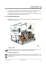
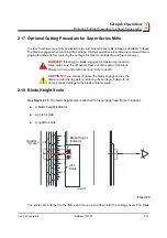
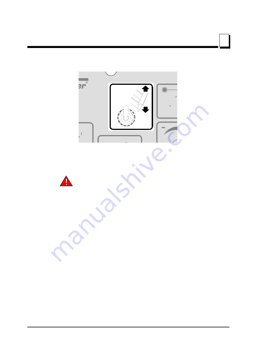
See Figure 2-7. 

When the blade reaches the end of the log, the arm will drop down to catch the board and drag it
back toward the operator as the saw head is returned.

DANGER!

 Keep all persons out of the path of returning boards.

Failure to do so will result in serious injury. 

Boards may not always return in the same path or location. If a board returns in a manner that
does not allow the sawyer or off-bearer to maintain control, it may be necessary to stop the
reverse motion of the saw head.

When the board return is to be used, a second person is required to remove the board as it is
returned. DO NOT attempt to use the board return feature when sawing alone.

To bypass the board return feature, push the toggle switch on the control panel up.

FIG. 2-7

3H0363

Содержание LT40 DH

Страница 1: ......

Страница 2: ......

Страница 3: ...y Setup Operation Maintenance Manual LT40 Series DH rev E2 04 Safety is our 1 concern Read and understand all safety information and instructions before oper ating setting up or maintaining this machine February 1998 Form 535 ...

Страница 4: ...e day they are ordered Second Day and Next Day shipping are available at additional cost If You Need Service From Europe call our European Headquarters and Manufacturing Facility in Kolo Poland at 48 63 2626000 From the continental U S call us toll free at 1 800 525 8100 Ask to speak with a Customer Service Representative Please have your vehicle identification number and your customer number read...

Страница 5: ...iana Weight Class A Under 3 000 lbs B 3 001 4 000 lbs C 4 001 5000 lbs Product No 1 LT15 2 LT20 4 LT40 Series 7 LT70 Series Length of the Trailer 20 20 Ft 24 24 35 35 Number of axles on the trailer Year of Manufacture Y 2001 Z 2002 A 2003 B 2004 C 2005 D 2006 State of Manufacture N Indiana P Poland Month of Manufacture A January B February C March etc Revision Level Sequence Number Ranging from 00...

Страница 6: ...or a description of the model number When you pick up your mill you will receive a customer number Both the VIN and your customer number expedite our service to you Please write these numbers below so you have quick easy access to them MODEL NUMBER DESCRIPTION Customer No Model No V I N Revision LT40 Basic Sawmill I D E25 Configuration Engine Motor ...

Страница 7: ...ic Schematic 1 20 1 18 LT40 Series DH Hydraulic Components 1 21 1 19 LT40 Series DH Hydraulic Hoses 1 22 SECTION 2 SETUP OPERATION 2 1 2 1 Stationary Sawmill Setup 2 1 2 2 Portable Sawmill Setup 2 3 2 3 Middle Track Cover 2 6 2 4 Replacing The Blade 2 7 2 5 Tensioning The Blade 2 8 2 6 Tracking The Blade 2 9 2 7 Starting The Engine or Motor 2 10 2 8 Board Return 2 11 2 9 Hydraulic Control Operatio...

Страница 8: ...tment 3 11 3 12 Clutch Handle Adjustment 3 14 3 13 Autoclutch Option Adjustment 3 15 3 14 Hydraulic System 3 16 3 15 Drive Bearing 3 17 3 16 Up Down System 3 18 3 17 Power Feed 3 20 3 1 SECTION 4 TROUBLESHOOTING GUIDE 4 1 4 1 Sawing Problems 4 1 4 2 Electrical Problems 4 3 4 3 Power Feed Problems 4 5 4 4 Power Feed Circuit Troubleshooting 4 7 4 5 Hydraulic Problems 4 8 4 6 Engine Motor and Drive P...

Страница 9: ...ide Arm Vertical Adjustment 5 12 5 8 Blade Guide Arm Horizontal Adjustment 5 13 5 9 Aligning the Blade Guides 5 15 5 10 Blade Deflection 5 16 5 11 Blade Guide Vertical Tilt Adjustment 5 17 5 12 Blade Guide Spacing 5 19 5 13 Horizontal Tilt Adjustment 5 20 5 14 Blade Guide Block Adjustment 5 21 5 15 Horizontal Adjustment of Side Supports 5 22 5 16 Vertical Adjustment of Side Supports 5 23 5 17 Clam...

Страница 10: ...ing stripes Read and observe all safety instructions before operating this equipment Also read any additional manufacturer s manuals and observe any applicable safety instructions including dangers warn ings and cautions Always be sure that all safety decals are clean and readable Replace all damaged safety decals to prevent personal injury or damage to the equipment Contact your local distributor...

Страница 11: ...own before moving cutting head from the rest position may result in serious injury WARNING Securely fasten the feet of a stationary sawmill to the floor before operating the sawmill Failure to do so may result in serious injury or death WARNING Always make sure the trailer is supporting the saw mill frame when operating a sawmill with adjustable outriggers Failure to do so may result in serious in...

Страница 12: ...r path for all necessary movement around the mill and lumber stacking areas Failure to do so will result in serious injury DANGER Always be sure the blade is disengaged and all per sons are out of the path of the blade before starting the engine or motor Failure to do so will result in serious injury DANGER Keep all persons out of the path of returning boards Failure to do so will result in seriou...

Страница 13: ...injury or death CAUTION Be sure the pivot rails turning arm clamp and toe boards are below bed level before loading a log onto the bed Failure to do so may result in machine damage or cause mis alignment CAUTION Before loading a log be sure the cutting head is moved far enough forward so the log does not hit it Failure to do so may result in machine damage CAUTION Always make sure the engine is ru...

Страница 14: ...er extinguisher 1 4 Sawmill Maintenance WARNING Always secure the cutting head with a chain or a brace before adjusting the up down chain The cutting head may fall causing severe injury or death WARNING Always secure the cutting head with a chain or a brace before adjusting the mast pads The cutting head may fall causing severe injury or death WARNING Always secure the cutting head with a chain or...

Страница 15: ...e vertical mast the pad spac ing may vary throughout the travel of the saw head Check the pad spacing at the top and bottom ends of the mast only Pads adjusted too tight will cause premature up down motor failure CAUTION It is important that the lower stop bolts are properly adjusted to secure the carriage on the track rail Failure to prop erly adjust the stop bolts can cause saw head damage espec...

Страница 16: ...cal View W M No Description 096317 CAUTION Read thoroughly the manual before operating the machine Observe all safety instructions and rules when operating the sawmill 099220 CAUTION Close all guards and covers before starting the machine 099219 Blade tension Turning the bolt clockwise will increase the blade tension and turning the bolt counterclockwise will decrease the tension 099220 099219 ...

Страница 17: ...ation HDSdoc091108 1 8 1 099223 Blade tension See manual 099221 CAUTION Keep all persons a safe distance away from work area when operating the machine 098176 CAUTION Keep away from debarker blade 099222 CAUTION Sawdust outlet Protect eyes TABLE 1 1 099223 099221 098176 ...

Страница 18: ...intenance 1 1 9 HDSdoc091108 Safety General Information 099542 CAUTION Trailer 086099 CAUTION Keep away hot parts 096321 Blade movement direction S12004G CAUTION Always wear safety goggles when operating the sawmill TABLE 1 1 099542 086099 ...

Страница 19: ...DSdoc091108 1 10 1 S12005G CAUTION Always wear protective ear muffs when operating the sawmill P11789 Aligning the blade on the wheels P85070 CE safety certification 099401 Russian safety certification S20097B 3300 RPM Motor rotation direction TABLE 1 1 099401 S20097B 3300 RPM ...

Страница 20: ...K1080 088181 Blade Pulley Belts B57 1 1 To insure proper blade tracking use Goodyear Dayco Super II or Browning belts only P04185 Power Feed Drive Belt AX35 015175 Up Down Drive Belt AX23 015257 Board Return Belt 3L190 015477 TABLE 1 2 Softwood Medium Hardwood Frozen Timber or Dense Hardwood 5 15HP Gas B275IH1030 B275IH741030 B375IH929 B375IH929 1 1 TRU SHARP F blades use a 9 29 profile 9 hook ang...

Страница 21: ...H 36 91 5 cm 21 6 4 m LT40 S DH with Optional 6 Bed Extension 2 36 91 5 cm 22 8 6 9 m LT40 M DH with Optional 6 Bed Extension 2 36 91 5 cm 27 8 2 m LT40 S DH with Optional 12 Bed Extension 2 2 Logs over 4400 lbs must be distributed so that neither the basic mill or extension is loaded beyond the 4400 lb maximum weight rating Loading logs heavier than 4400 lbs 1996 Kg on a mill equipped with bed ex...

Страница 22: ...ders 1498 cm3 25HP Electric 2 2 The electric motors supplied on Wood Mizer sawmills carry a rating assigned by the motor manufacturer for the continuous duty operation of the motor potentially 24 hours per day day after day This rating is useful in sizing motors for use in applications like blowers for heating and ventilation that are never cycled off except for system maintenance Indukta SA Polan...

Страница 23: ...not necessarily to noise levels in the workplace Although there is a relation between emission levels and exposure levels it is not possible to determine with certainty if preventives are needed or are not needed The factors affecting a current level of noise exposure during work are inter alia room characteristics and characteristics of other noise sources e g number of machines and machining ope...

Страница 24: ... from hitch to chain bracket Width 2 2 Width from fender to fender With Operating Position with Loading Arms Height 3 3 Height from ground to mast Placing head in maximum position will add to total height Weight Weight w Trailer LT40 S DH 21 11 6 7 m 6 6 2 m 8 2 2 5 m 7 8 2 4 m 3291 lbs 1481 kg 3716 lbs 1672 kg LT40 M DH 26 2 8 m 6 6 2 m 8 2 2 5 m 7 8 2 4 m 3491 lbs 1571 kg 3916 lbs 1762 kg TABLE ...

Страница 25: ... DH are shown below Hydraulic Pump M 300 0230 Monarch Pressure Rating 17 25MPa 2500 PSI Max Pressure 19MPa 2750 PSI TABLE 1 4 FIG 1 1 Engine Drive Assembly Outer Blade Guide Arm Blade Guide Rollers Blade Tensioner Clutch Brake Handle Control Box Hydraulic Control Box Trailer Hitch W Optional Trailer Pivot End Rail Hydraulic Log Loader Optional Trailer Axle Adjustable Outrigger Leg W Optional Trail...

Страница 26: ... H6 H17 H12 H13 H16 H15 H2 H1 H3 H8 H7 H13 H4 H10 CLAMP IN OUT CLAMP UP DOWN CLAMP UP DOWN CLAMP IN OUT TURNER LOADER ARM RELIEF VALVE SETTING 2000 PSI RELIEF VALVE SETTING 2250 PSI TOEBOARD TOEBOARD FRONT TOEBOARD REAR TOEBOARD TURNER SIDE SUPPORT LOADER ARM LOADER ARM H5 H18 H11 3 8 3 x 7 7 8 1 x 10 1 x 6 1 x 6 2 x 6 2 1 2 x 8 3 x 8 3 x 8 C1 C2 C3 C4 C5 C6 C7 C8 M1 M2 P1 P2 V1 V2 V3 V4 V5 F1 ...

Страница 27: ...08 1 18 1 FIG 1 3 HYDRAULIC LAYOUT DIAGRAM C1 C2 C3 H3 H8 H7 H10 H11 H12 H13 H14 H15 H16 H17 H18 H9 H6 H5 H4 C4 C5 C6 C7 C8 V1 M1 P1 F1 M2 P2 V2 V3 V4 V5 H2 H1 Shown with handles down Clamp In Out Clamp Up Down Turner Side Supports Front Toe Board Rear Toe Board Log Loader HD0136B Crossflow Hose 3 8 ...

Страница 28: ... Up Down Turner Side Support Toeboard Loader Arms Toeboard Front Toeboard Rear Front Clamp Up Down Front Clamp In Out Rear Clamp In Out Rear Clamp Up Down P1 H1 C1 C2 C3 C4 C5 C6 C7 C8 C9 C10 C9 C10 H2 H6 H7 H8 H9 H17 H18 H3 V2 V3 H4 H5 H10 H11 H12 H13 H13 V4 V5 H13 H14 H15 V1 V6 H27 H19 H20 H21 H22 H23 H24 H25 H26 Toeboard Rear Clamp In Out Rear Clamp Up Down Front Clamp In Out Front Clamp Up Dow...

Страница 29: ...ort Toeboard Toeboard Loader Arms Turner Toeboard Front Toeboard Rear Loader Arm Clamp Up Down I Clamp In Out I II III P1 H1 C1 C2 C3 C4 C5 C6 C7 C8 C10 C9 C9 C9 H2 H6 H7 H8 H9 H17 H18 H3 V2 V3 H4 H5 H10 H11 H12 H13 H13 V4 V5 H13 H14 H15 V1 C10 C10 Clamp Up Down II Clamp Up Down III Clamp Up Down I Clamp Up Down II Clamp Up Down III V6 Clamp In Out I Clamp In Out II Clamp In Out III H27 H35 H36 H4...

Страница 30: ...mm Stroke C4 CJ S270 16 5 0 28 152 088678 Hyd Cylinder 50mm Bore X 152mm Stroke C5 C6 CJ S170 16 4 0 25 152 088681 Hyd Cylinder 40mm Bore x 152mm Stroke C7 C8 CJ S95 16 70 32 203 088680 Hyd Cylinder 70mm Bore X 203mm Stroke C9 CJ7F 16 40 2 2 UE2 40W 091346 Hydraulic Cylinder C10 SJ2F 16 40 2 2 80 093880 Hydraulic Cylinder P1 P2 M300 0230 P12701 Hydraulic Pump With Motor V1 HDS10 6 6 015260 Valve 6...

Страница 31: ... Toe Board Base LT40S 087790 3 83m 151 1 4 Front Toe Board Base LT40M 087776 H7 Pink 4 2m 166 3 8 Side Support Cylinder Base LT40S 087791 4 77m 188 3 8 Side Support Cylinder Base LT40M 087777 H8 Plain 4 2m 166 3 8 Side Support Cylinder Top LT40S 087791 4 77m 188 3 8 Side Support Cylinder Top LT40M 087777 H9 White 3 68m 145 3 8 Clamp Cylinder Top LT40S 087792 4m 157 3 8 Clamp Cylinder Top LT40M 087...

Страница 32: ...IN OUT CYLINDER TOP A DH5 094778 H21 RED 150 3 8 FRONT LOG CLAMP UP DOWN CYLINDER BOTTOM A DH5 094779 H22 BLUE 150 3 8 FRONT LOG CLAMP UP DOWN CYLINDER TOP A DH5 094779 H23 WHITE 236 3 8 REAR LOG CLAMP IN OUT CYLINDER BOTTOM A DH5 094780 H24 ORANGE 236 3 8 REAR LOG CLAMP IN OUT CYLINDER TOP A DH5 094780 H25 RED 220 3 8 REAR LOG CLAMP UP DOWN CYLINDER BOTTOM A DH5 094781 H26 BLUE 220 3 8 REAR LOG C...

Страница 33: ...IN OUT CYLINDER T FITTING TOP AH7 095214 H37 ORANGE 7 00 1 4 THIRD CLAMP IN OUT CYLINDER BOTTOM AH7 095215 H38 WHITE 7 00 1 4 THIRD CLAMP IN OUT CYLINDER TOP AH7 095215 H39 ORANGE 2 50 1 4 FIRST SECOND CLAMP IN OUT CYLINDER BOTTOM AH7 095216 H40 WHITE 2 50 1 4 FIRST SECOND CLAMP IN OUT CYLINDER TOP AH7 095216 H41 ORANGE 1 20 1 4 FIRST SECOND CLAMP IN OUT CYLINDER BOTTOM AH7 095217 H42 WHITE 1 20 1...

Страница 34: ... should be rated to support 6350 lbs sq ft at each sawmill foot position NOTE Make sure the unit is level before securing It IS possible to twist the mill frame by jacking one foot higher than the others WARNING Securely fasten the feet of a stationary sawmill to the floor before operating the sawmill Failure to do so may result in serious injury or death FIG 2 1 HD0131ce_d 1790 820 2590 850 2820 ...

Страница 35: ...wing the rest pin down below bed level 3 Use the carriage forward reverse switch left side of control box to move the cutting head toward the front end of the mill The hydraulic control levers become operational when the contacts at the bottom of the carriage touch the power strip on the frame tube The hydraulic control levers will only work when the cutting head is close enough to the front end o...

Страница 36: ...ARNING Always make sure the trailer is supporting the saw mill frame when operating a sawmill with adjustable outriggers Failure to do so may result in serious injury or death The adjust able outriggers are intended to support the saw frame with assis tance from the trailer 1 Pull the hand brake to fix the machine 2 Unhitch the mill from the vehicle 3 Lower and set the front outriggers Manually pu...

Страница 37: ...HDSdoc091108 2 4 2 CAUTION If setup sawmill on a boggy terrain such as deep mud or sand place the board or metal plate under each outrigger leg to prevent it from sinking FIG 2 2 OUTRIGGER ADJUSTMENT Adjustment Bolt Outrigger Leg Travel Lock Pin Locking Pin ...

Страница 38: ...e rest position may result in serious injury 6 Remove the fenders by lifting them out of the slots CAUTION To prevent fender damage remove fenders before operating sawmill or loading logs 7 Use the carriage forward reverse switch left side of control box to move the cutting head toward the front end of the mill Lower and set the remaining rear outriggers 8 Level the sawmill by adjusting the outrig...

Страница 39: ...r from its storage position 3 Soak the felt wiper with Dexron III transmission fluid 10W30 motor oil or 3 in 1 turbine oil 4 Install the middle track cover so it fits against the rail and secure with two thumb screws See Figure 2 4 CAUTION Install the track cover so that it lightly touches the track rail If the wiper presses too firmly against the rail it can cause the power feed to bind FIG 2 4 I...

Страница 40: ... the blade tension until the wheel is pulled in and the blade is lying loose in the blade housing Lift the blade out of the blade housing When installing a blade make sure the teeth are pointing the correct direction The teeth should be pointing toward the operator side of the mill when you are looking at the blade below the blade guides Install the blade so it is lying around the wheels Position ...

Страница 41: ...erature changes will cause tension to change Adjust the tension handle as necessary to maintain the recommended tension level CAUTION Changes in temperature could cause increased pressure in the blade tensioner and loss of fluid from the gauge Release the blade tension when the mill is not in use to avoid damage to the tensioner FIG 2 5 Blade Type Acceptable Range Ideal Tension B375IH929 12 4 14 5...

Страница 42: ...2 6 Position 1 1 4 wide blades so the gullet is 3 0 mm 0 12 out from the edge of the blade wheel 1 0 mm 0 04 Position 1 1 2 blades so the gullet is 4 5 mm 0 18 out from the edge of the blade wheel 1 0 mm 0 04 5 To adjust where the blade travels on the blade wheels use the cant control shown in Figure 2 5 If the blade is too far out back the blade onto the wheel by turning the cant control counterc...

Страница 43: ...s are in place and secured before operating or towing the sawmill Failure to do so may result in serious injury Be sure the blade housing and pulley covers are in place and secure Use the safety retainer pin and cable to fasten blade housing covers DANGER Always be sure the blade is disengaged and all per sons are out of the path of the blade before starting the engine or motor Failure to do so wi...

Страница 44: ... designed and intended to assist in the removal of boards only Standing on the table may result in serious injury Sawmills can be equipped with a board return system This system consists of an arm on the saw head controlled by a toggle switch on the control panel A board return table is also provided to catch the board as it is removed from the log To activate the board return turn the key switch ...

Страница 45: ...ill result in serious injury Boards may not always return in the same path or location If a board returns in a manner that does not allow the sawyer or off bearer to maintain control it may be necessary to stop the reverse motion of the saw head When the board return is to be used a second person is required to remove the board as it is returned DO NOT attempt to use the board return feature when ...

Страница 46: ...ers to load clamp turn and level logs DH5 and DH7 hydraulic units have four additional levers for controlling the Pull Down clamps In sawmills equipped with DH5 hydraulic system individual Pull Down clamps are controlled with separate levers In sawmills with DH7 hydraulic system in out movement of individual clamps is controlled with the same lever and up down movement of individual clamps is cont...

Страница 47: ...mills equipped with DH5 hydraulic system See Figure 2 10 Clamping cants on sawmills equipped with DH7 hydraulic system RYS 2 9 RYS 2 10 A DH3 Front Clamp Up Down HD0185 Front Clamp In Out Rear Clamp Up Down Rear Clamp In Out A DH3 Clamp I Up Down Clamp II Up Down Clamp I II III In Out Clamp III Up Down HD0186 094970 ...

Страница 48: ... slack in the chain 4 Unchain the loading arm from the turner arm 5 Lower the turner lever to completely lower the turner arm Notice that after the turner arm is all the way down the side support braces will begin to lower Release the turner lever after the turner arm is lowered but before the side supports begin to lower This stops the log being loaded from dam aging the turner and or falling off...

Страница 49: ...y centered with the sawmill bed The log turner will operate much easier if the log is centered on the sawmill bed 3 Raise the loader lever to raise the log onto the sawmill bed Simply let the loader rise until the log rolls onto the mill bed 4 Lower the loading arm Leave the loading arm about halfway up while squaring the log This will stop the log from rolling off the side of the mill WARNING Alw...

Страница 50: ...g 6 Disengage the clamp 7 The log can be turned now Repeat steps 4 through 7 until the log is turned as desired To Turn Logs Optional Procedure For Hydraulic Mills Except Only If you are turning a small cant on a Super Series mill you may opt to use the clamp to turn the cant 1 Lower the clamp up down lever to lower the clamp below bed level 2 Raise the clamp in out lever to move the clamp in bene...

Страница 51: ...elow the level of your first few cuts To Level A Tapered Log Use the toe board lever s to raise either end of a tapered log if desired Raise the appropriate lever to raise the front or rear toe board until the heart of the log measures the same distance from the bed rails at each end of the log Pull Down Clamps When a cant is being cut internal stress in the wood may cause the cant to deform sligh...

Страница 52: ...ld the switch in position until the cutting head reaches the desired height then release The up down switch is designed to return to the neutral or off position when released If the switch remains engaged manually move the switch to the neutral or off position Repair the up down drum switch See Section 4 2 CAUTION Always make sure the up down switch moves to the neutral or off position when releas...

Страница 53: ...4 mm 2 Use the blade guide toggle switch on the control panel to adjust the outer blade guide as neces sary Push the switch to the left to move the arm in Push the switch to the right to move the arm out See Figure 2 12 3 Use the blade guide toggle switch to readjust the outer blade guide as you are cutting in order to keep the guide within 1 2 5 cm of the log Be sure to adjust the arm back out be...

Страница 54: ... engine manual DANGER Make sure all guards and covers are in place and secured before operating or towing the sawmill Failure to do so may result in serious injury Be sure the blade housing and pulley covers are in place and secure Use the safety retainer pin and cable to fasten blade housing covers Be sure the blade housing and pulley covers are in place and secure before starting the engine or m...

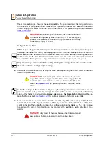
Страница 55: ...d Operation See Figure 2 14 The power feed system moves the carriage forward and backward by using two switches on the control panel Carriage Feed Rate The carriage feed rate switch controls the speed at which the carriage travels forward Turn the switch clockwise to increase speed Turn it counterclockwise to reduce speed Carriage Forward and Reverse The carriage forward reverse switch controls th...

Страница 56: ...e carriage feed rate switch counter clockwise until the carriage stops moving 2 Throw the clutch brake lever UP to stop the blade and drop the engine to idle Remove the board from the top of the log CAUTION Be sure to stop the blade when returning the car riage This will not only prevent the blade from being pulled off and ruined by a wood sliver but also will increase the life of the blade See Se...

Страница 57: ...he clutch brake lever or remote blade switch to start the blade spinning 4 Start the water lube if necessary to prevent sap buildup on the blade See Section 2 19 5 If you want to use the board return function push the toggle switch on the control panel down See Section 2 8 6 Feed the blade into the log slowly See Section 2 14 Once the blade completely enters the log increase the feed rate as desir...

Страница 58: ...ember that the blade cuts a 1 16 1 8 1 6 3 2 mm wide kerf If you want 1 25 4 mm thick boards lower the carriage 1 1 16 1 1 8 27 28 6 mm for each board 2 16 Edging The following steps guide you through edging boards on the Wood Mizer sawmill 1 Raise the side supports to 1 2 the height of the flitches or the boards that need to be edged 2 Stack the flitches on edge against the side supports 3 Clamp ...

Страница 59: ...roduction rates make sure the off bearer stays out of the path of the blade Failure to do so will result in serious injury or death CAUTION If you choose to leave the blade engaged raise the blade to clear the log before returning the carriage Failure to do so may cause damage to the blade and or sawmill 2 18 Blade Height Scale See Figure 2 15 The blade height scale is attached to the carriage hea...

Страница 60: ...nkage of the lumber The yellow area on the scale identifies where the blade could encounter a side support or log clamp Check that these items are below the blade level before sawing The Quarter Scale See Table 2 2 Two quarter scales are provided with four sets of marks Each set repre sents a specific lumber thickness Saw kerf and shrinkage allowance are included but actual board thickness will va...

Страница 61: ...rees and repeat 2 19 Water Lube Operation See Figure 2 16 The Water Lube System keeps the blade clean Water flows from a 5 gallon 18 9 liter bottle through a hose to the blade guide where the blade enters the log A valve in the bottle cap controls the amount of water flow Super models include a solenoid valve that will automatically start the water flow when the power feed is activated in the forw...

Страница 62: ...g The Wood Mizer trailer package makes transporting your sawmill easy and convenient To get your sawmill ready for towing follow these instructions CAUTION If the weight of the sawmill exceeds 3 000 lbs 1361 Kg for any reason an auxiliary braking system such as electric brakes must be used Failure to do so may result in severe machine damage 1 Move the saw carriage to the front end of the sawmill ...

Страница 63: ...rack rail Failure to prop erly adjust the stop bolts can cause saw head damage especially during mill transportation 9 If necessary adjust the two stops located at the bottom of the mast so the saw head contacts them after it is lowered 3 4 19mm past where it contacts the rest pin See Figure 2 18 10 Engage the clutch brake lever This keeps the drive belt tight and the motor from bouncing while FIG...

Страница 64: ... secure the saw head can result in severe machine damage Be sure the blade housing and pulley covers are in place and secure Use the safety retainer pin and cable to fasten blade housing covers 12 Remove all loose objects from the bed of the mill Store the outrigger jack handle in the bracket provided on the rear loading side outrigger guide Reel in the winch cable Remove the winch han dle 13 Plac...

Страница 65: ...ther maintenance procedures 3 1 Wear Life See Table 3 1 This chart lists estimated life expectancy of common replacement parts if proper maintenance and operation procedures are followed Due to the many variables which exist during sawmill operation actual part life may vary significantly This information is provided so that you may plan ahead in ordering replacement parts Part Description Estimat...

Страница 66: ...ffected even if the body of the block is adjusted properly to the blade At this point the block should be replaced If you have access to the appropriate equipment you can grind or mill the blocks to a new flat surface and reuse them It is recommended you develop a routine schedule for replacing the blade guide blocks based on your sawing conditions and experience 3 Check the inserts are properly s...

Страница 67: ...el to the blade After adjusting the drive side blade guide block insert up check the deflector If necessary loosen the two deflector mounting screws and adjust the deflector so it does not touch the blade See Figure 3 2 4 Make sure the blade screw in the top center of the C frame is 1 16 1 5 mm below the bottom of the blade If not loosen the nut and adjust the screw as necessary Check the screw ev...

Страница 68: ...er feed belt cover 3 4 Carriage Track Wiper Scrapers See Figure 3 3 1 Clean the upper and lower track rails to remove any sawdust and sap buildup every eight hours of operation Lubricate the lower track rail by wiping it with Dexron III ATF 2 Remove sawdust from the upper cam housings Loosen the thumb screws on the upper cam housing covers and open Brush any sawdust buildup from the housings 3 Che...

Страница 69: ...Maintenance Carriage Track Wiper Scrapers Maintenance HDSdoc091108 3 5 3 FIG 3 3 ...

Страница 70: ...witches Lubricate the up down and power feed drum switch contacts inside the control panel every fifty hours of operation Use only contact grease supplied by Wood Mizer Remove the control panel cover Use a cotton swab to apply grease to the switch contact ends WARNING Drum switch grease contains Petroleum Hydrocar bon Lubricant Eye and skin irritant If introduced into eyes flush with water for at ...

Страница 71: ...hains with Dexron III ATF every fifty hours of operation CAUTION Do not use chain lube It causes sawdust buildup in chain links 4 Lubricate the board return pivot every fifty hours of operation with a NLGI No 2 grade lithium grease Apply grease to the grease fitting on the board return pivot tube 5 Check the mill alignment every setup See Section 5 Alignment 6 Make sure all safety warning decals a...

Страница 72: ...blade housing covers blade and idle side blade wheel Push the idle side shaft housing all the way in to collapse the rear tensioner piston and fully extend the front piston The front piston should reach the threaded area of the piston guide NOTE If the hydraulic fluid level is extremely low collapsing the rear piston may not fully extend the front piston If it does not finish the fill procedure in...

Страница 73: ...d check them for wear Rotating the belts every 50 hours will give you longer belt life Replace belts as necessary Use only B57 belts manufactured by Goodyear or Browning 2 Periodically check all belts for wear Replace any damaged or worn belts as needed 3 10 Brake Strap Adjustment Check the brake strap for wear every 200 hours of operation Replace if damaged or worn Also check and adjust the brake...

Страница 74: ... Strap Adjustment 3 3 10 HDSdoc091108 Maintenance See Figure 3 6 Loosen the two nuts on the upper brake strap bracket Slide the bracket and brake strap down until snug Retighten the bolts Replace the belt cover FIG 3 6 ...

Страница 75: ...elt covers located underneath the engine 2 For Manual Clutch Handle Loosen the drive belt turnbuckle jam nuts Turn the turnbuckle coun terclockwise as viewed from the top to tighten the belt clockwise to loosen the belt See Figure 3 7 3 For Autoclutch Option Place a wrench on the flats at the top of the turnbuckle Use a second wrench to turn the bottom most jam nut clockwise as viewed from the bot...

Страница 76: ...ed The throttle linkage should NOT affect engine RPM while the clutch brake handle is disengaged NOTE A properly adjusted throttle will extend the cable spring 1 4 to 3 8 6 4 9 5 mm when running and have a slight amount of slack in the cable when idling Always be sure to check the drive belt support after adjusting drive belt tension Periodically check all belts for wear Replace any damaged or wor...

Страница 77: ...AND to hold the drive belt away from the engine pulley when the clutch handle is disen gaged up position See Figure 3 9 To adjust the drive belt support 1 Make sure the motor is not running Loosen the adjustment bolts 2 Position the bracket so that the prong is close to but does not touch the drive belt with the clutch handle engaged 3 Retighten the adjustment bolts 25 27 pound feet 34 37 newton m...

Страница 78: ...e turnbuckle See Section 3 13 for optional Autoclutch adjustment 1 Remove the blade from the sawmill 2 Remove the inner belt guard and pull the clutch handle down to engage the drive belts 3 Hold a straight edge between the bottom and top pivot centers and measure the distance to the middle pivot 4 Adjust the clutch handle turnbuckle until the center of the middle pivot is 7 16 from the straight e...

Страница 79: ... blade from the sawmill 2 Remove the inside belt guard and push the Autoclutch switch up to engage the drive belts 3 With the belts engaged place a straight edge between the upper and lower clutch pivot centers Measure the distance to the middle pivot 4 Adjust the Autoclutch turnbuckle so the middle pivot is positioned 7 16 behind the straight edge See Figure 3 11 FIG 3 11 3H0505 Remote Clutch Tur...

Страница 80: ...prevent fluid wear See Figure 3 12 If you are operating in temperatures 20 to 100 F 29 to 38 C use an all weather hydraulic fluid such as Exxon Univis J26 For alternate fluids and or other temperature ranges refer to the chart below Operating above the recommended temperature range of a fluid could result in excessive pump wear Operating below the recommended temperature range could result in redu...

Страница 81: ...housing every 500 hours of operation Remove the top and bottom oil plugs Pour an Automatic Transmission Fluid ATF such as UNIVIS J26 or Dexron III ATF into the top hole until it begins to flow from the bottom hole Reinstall the square oil plug to the bottom hole and the vented oil plug to the top hole See Figure 3 13 FIG 3 13 500 ...

Страница 82: ...uper model up down systems feature a spring loaded belt design Belt tension is automatically maintained and requires no adjustment Replace the belt when adequate belt tension can no longer be obtained WARNING Always secure the cutting head with a chain or a brace before removing the up down motor belt The cutting head may fall causing severe injury or death FIG 3 14 1000 3H0016B Up Down Gear Reduc...

Страница 83: ...can be deflected 3 4 1 9cm forward and 3 4 1 9cm backward with a 5 lb 2 3 Kg deflection force WARNING Always secure the cutting head with a chain or a brace before adjusting the up down chain The cutting head may fall causing severe injury or death CAUTION Do not over tension the chain Over tensioning the chain may lead to early failure of the gear reducer See Figure 3 15 4 Check the up down gearb...

Страница 84: ...ts Place a wrench on the jam nut and turn the adjustment bolt clockwise to tighten the belt Retighten the motor bolts and replace the feed motor cover 2 Adjust the power feed chain as needed Measure the power feed chain tension with the saw head all the way toward the front of the mill Use the two lock nuts at the rear of the mill to tighten or loosen the power feed chain Adjust the chain until it...

Страница 85: ...Maintenance Power Feed Maintenance HDSdoc091108 3 21 3 See Figure 3 17 FIG 3 17 Feed Chain Adjustment Nuts 3H0018B ...

Страница 86: ...de Roller Performance See Section 3 2 Remove Excess Sawdust From Blade Wheel Housings And Sawdust Chute See Section 3 3 Check Blade Screw See Section 3 2 EVERY 8 HOURS Clean And Lubricate Track See Section 3 4 Remove Sawdust From Upper Cam Housings See Section 3 4 Clean Sawdust From Hydraulic Loader Fuses Battery Box Lid Track Cover See Section 3 3 EVERY 25 HOURS Clean And Lubricate Upper Track Wi...

Страница 87: ... chains See Section 3 7 See Section 3 16 See Section 3 17 Check belt tensions See Section 3 11 See Section 3 16 See Section 3 17 Check brake strap tension See Section 3 10 Rotate drive idle blade wheel belts Check all belts for wear See Section 3 9 Check feed up down chain tensions See Section 3 16 See Section 3 17 Check up down gear box fluid level See Section 3 16 Lubricate blade tensioner handl...

Страница 88: ...l chains See Section 3 7 See Section 3 16 See Section 3 17 Check belt tensions See Section 3 11 See Section 3 16 See Section 3 17 Check brake strap tension See Section 3 10 Rotate drive idle blade wheel belts Check all belts for wear See Section 3 9 Check feed up down chain tensions See Section 3 16 See Section 3 17 Check up down gear box fluid level See Section 3 16 Lubricate blade tensioner hand...

Страница 89: ...gs Oil chains See Section 3 7 See Section 3 16 See Section 3 17 Check belt tensions See Section 3 11 See Section 3 16 See Section 3 17 Check brake strap tension See Section 3 10 Rotate drive idle blade wheel belts Check all belts for wear See Section 3 9 Check feed up down chain tensions See Section 3 16 See Section 3 17 Check up down gear box fluid level See Section 3 16 Lubricate blade tensioner...

Страница 90: ...gs Oil chains See Section 3 7 See Section 3 16 See Section 3 17 Check belt tensions See Section 3 11 See Section 3 16 See Section 3 17 Check brake strap tension See Section 3 10 Rotate drive idle blade wheel belts Check all belts for wear See Section 3 9 Check feed up down chain tensions See Section 3 16 See Section 3 17 Check up down gear box fluid level See Section 3 16 Lubricate blade tensioner...

Страница 91: ...gs Oil chains See Section 3 7 See Section 3 16 See Section 3 17 Check belt tensions See Section 3 11 See Section 3 16 See Section 3 17 Check brake strap tension See Section 3 10 Rotate drive idle blade wheel belts Check all belts for wear See Section 3 9 Check feed up down chain tensions See Section 3 16 See Section 3 17 Check up down gear box fluid level See Section 3 16 Lubricate blade tensioner...

Страница 92: ...wheels Change blade wheel belts B 57 Poor sharpening techniques See Sharpener Manual Tension too tight Tension blade to recom mended specifications Blade Does Not Track Right on Drive Wheel Cant adjustment is incorrect Readjust Flat worn belts Replace B 57 belts Blade Guides Do Not Spin While Cutting Frozen bearings Replace bearings Stiff bearings Grease bearings Blade Does Not Stop Immedi ately A...

Страница 93: ...ted Adjust up down chain Vertical wear pads are too tight Adjust pads Drive belt s loose Adjust belts Lumber Is Not Square Vertical side supports not square to bed Adjust side supports Blade not parallel to bed rails Adjust bed rails parallel to blade Sawdust or bark between cant and bed rails Remove particles Tooth set problems Resharpen and reset blade Sawdust Builds Up On Track Excessive oiling...

Страница 94: ...se wire Check for loose wire or termi nal connections Power Feed Motor Does Not Work Sawdust buildup in the power feed pulleys Sawdust buildup puts mechan ical bind on power feed which causes automatic motor pro tection circuit to activate Remove sawdust from pulleys and operate normally If motor does not operate after sawdust removal reset 70 amp circuit breaker on the front of the con trol box U...

Страница 95: ...on battery post Remove connection and clean posts Battery Will Not Stay Charged Key switch left ON Turn switch OFF when not in use Short in system Visually check for bare wires and or have checked Charging system not function ing Have charging system checked by authorized dealer Bad battery cells Check fluid levels and add proper solution Idle improper Adjust low end RPM per engine manual Loose al...

Страница 96: ...and lubricate with contact grease supplied by Wood Mizer Drum switch contacts are bad Check that contacts are in good condition and positively close cir cuit Components are loose or wires are broken Replace or repair PC board Power Feed Is Jerky When Shaft Of Feed Rate Dial Is Moved Back And Forth Variable speed switch is bad perform the variable speed switch test Replace variable speed switch Pow...

Страница 97: ...restarting Chain is dragging Make sure chain is centered on cam follower bearing Clean and lubricate chain Adjust chain ten sion Allow motor to cool before restarting Chain is improperly tensioned Adjust chain tension Allow motor to cool before restarting Seat load is excessive Check seat bearings for freedom of movement Loosen clamping screw 1 4 turn Allow motor to cool before restarting Power fe...

Страница 98: ...vervoltage condition This can be caused by a defective alternator not regulating voltage properly or a bad connection The OV light will come on and deactivate the power feed control output until the problem is corrected OL This light indicates an extreme overload condition of the power feed motor caused by a mechanical bind or a short in the wiring between the motor and circuit board The OL light ...

Страница 99: ...arnish or loose wires Clean as necce sary Blown fuse Replace Low or dead battery Test battery amperage capa bility such as low battery charge low alternator ouput defective voltage regulator bad battery cell battery age deterioration etc Replace or recharge as necessary Defective pump motor Remove motor from pump and inspect Repair or replace as necessary Poor cable connection Check cable connecti...

Страница 100: ... tacts are not properly adjusted Locate the valve switch at the bottom of the valve assembly Use a 3MM allen wrench to loosen the set screw on each of the five switch contacts Press each contact to the valve block and tighten the contact set screw to secure in place CAUTION Do not overtighten NOTE Do not adjust the valve switch or switch spring they have been preset at the factory ...

Страница 101: ...low fluid to warm up Syn thetic fluids are available that allow for hydraulic operation in cold weather conditions Mobil SHC 526 Pump Motor Runs Continu ously When Power Contact Is Made Solenoid is stuck closed Tapping the solenoid may solve this problem tempo rarily Replace solenoid Fluid Leaks From Around Cyl inder Piston Ram Worn seals Replace seals in cylinder Check piston ram for abrasive wel...

Страница 102: ...d weather conditions Mobil SHC 526 Hydraulic Turner Goes Up Before Or At Same Time As Side Supports Spring weakening in sequence valve Locate sequence valve at top of turner cylinder Turn heavy spring in about 1 4 turn Dirt in sequence valve Remove sequence valves and clean thoroughly with kero sene NOTE Be sure to reas semble the valve and install it in its original position on the cylinder Retai...

Страница 103: ...rical 1 Remove the drive belt from the power feed drive pulley 2 Turn the key switch to the ACC position Put the carriage forward reverse switch into the forward position and turn the feed rate dial through all speeds If the power feed motor runs properly at all speeds the problem is a mechanical one instead of an electrical one 4 8 Power Feed Mechanical Test 1 Remove the weight from the track rol...

Страница 104: ...arger or jumper cables to raise the saw head from the towing position so the battery box lid can be removed CAUTION The fuse stud extension is designed to provide enough power to raise the saw head only Do not attempt to start the engine or operate any other electrical function until direct bat tery charging can be performed Do not attempt to move the saw head by attaching jumper cables from a sec...

Страница 105: ...d and connect the positive cable directly to the positive battery terminal 10 Connect the negative cable to a grounded metal surface 11 After the battery is completely recharged remove the negative charger cable from ground Remove the positive cable from the battery and replace the battery box lid 4 10 Circuit Breaker Operation Sawmill controls are equipped with manual reset circuit breakers to pr...

Страница 106: ...reaker Operation 4 4 15 HDSdoc091108 Troubleshooting Guide FIG 4 3 External Power Feed Circuit Breaker External Up Down Circuit Breaker 3H0550 2 Internal Circuit Breakers Remove Panel Blade Guide Accessory Ignition Start Board Return ...

Страница 107: ...he lower track rollers if neces sary See Section 5 18 3 Check and adjust the vertical alignment of the blade guide arm See Section 5 7 4 Check and adjust the horizontal alignment of the blade guide arm See Section 5 8 5 Check and adjust the vertical angle of the blade guides See Section 5 11 6 Check and adjust the horizontal angle of the blade guides See Section 5 13 7 Check and adjust the spacing...

Страница 108: ...st the two end outriggers on the main frame tube down just enough to lift weight from the trailer tire All Portable Sawmills Adjust the two outer outriggers down just so they touch the ground but do not bear weight See SECTION 2 Setup Operation for additional setup information 5 3 Blade Installation And Alignment See Figure 5 1 Install a blade and apply the appropriate tension See Section 2 4 Blad...

Страница 109: ...tom of the wheel If it does not loosen and tighten the appropriate adjustment screws on the wheel shaft See Figure 5 2 The blade wheels should be adjusted so that the gullet of 1 1 4 blades ride 3 0 mm 0 12 out from the front edge of the wheels 1 0 mm 0 04 The gullet of 1 1 2 blades should ride 4 5 mm 0 18 from the front edge of the wheels 1 mm 0 04 Do not let the teeth ride on the wheels To adjus...

Страница 110: ... the back plate Loosen the jam nuts on the horizontal adjustment bolts Tighten the adjustment bolts to spread the plates apart and bring the blade forward If the blade is running too far to the front loosen the jam nuts on the horizontal adjustment bolts and back the adjustment bolts out Tighten the hex nuts on the long U bolt on the back side of the back plate Be sure to tighten all nuts against ...

Страница 111: ... engine side of the mast are referred to as the inner pads The pads on the control side of the mast are referred to as the outer pads NOTE Shims are often used around the clamping bolts between the C frame support bracket and the mast v brace The shims align the v brace to the mast so that the entire face of each slide pad makes contact with the mast Be sure to keep these shims in place when perfo...

Страница 112: ...3 Loosen the upper locking bolts and turn the adjusting bolt as necessary to provide the pad spacing described in Step 1 4 Lower the saw head to the bottom of the vertical mast Check the bottom set of four pads There should be a small gap between one of the outer pads and the mast rail The gap should be just wide enough to slide a business card through The inner two pads should be touching the mas...

Страница 113: ...djust the bottom track rollers 3 Check the inside lower rollers Both inside rollers should touch the rail so that you cannot spin them by hand If the rollers are not adjusted evenly and you can spin either one adjust the hori zontal nuts until the roller cannot be spun by hand Check the other roller and adjust if necessary Adjust both inside rollers until each evenly supports the carriage and you ...

Страница 114: ...he horizontal adjustment nuts evenly to adjust the inner lower rollers to tilt the saw head until the blade is parallel 1 0 mm to the pivot rail support on the outside NOTE Adjustments of the lower track rollers change the angle between the cutting head and saw mill bed rails Only small adjustments of the lower track rollers should ever be needed 10 After the lower track rollers are adjusted prope...

Страница 115: ...e saw head back to power the hydraulics and move the clamp all the way out Position the blade over the clamp tube again and measure from the inner end of the clamp tube to the bottom of the blade 4 If the clamp tube is level the measurement to the blade at both ends will be the same within 1 16 1 5 mm If adjustment is needed loosen the four mounting bolts at the outer end of the clamp tube and adj...

Страница 116: ...ke this measure ment at each end of the pivot rail 9 The two measurements should be 15 375 mm 10 Loosen the locking set screws and turn the inner height adjustment nut to adjust the height of the inner end of the pivot rail See Figure 5 8 11 Loosen the jam nut and turn the outer adjustment bolt to adjust the height of the outer end of the pivot rail 12 Move the saw head so the blade is positioned ...

Страница 117: ...ts and turn the adjustment bolts to move the bed rails to the blade if necessary 15 Retighten the clamping bolts and adjustment bolts 16 Without adjusting the saw head height check the three remaining main bed rails and the rear pivot rail Adjust them so that all measure the same distance from the blade at both ends of the bed rail FIG 5 9 ...

Страница 118: ...f full closed Measure again from the top of the bed rail to the arm 5 Adjust the arm so that the measurement from the top of the bed rail to the arm in the closed posi tion is the same as the measurement from the top of the bed rail to the arm in the open position If the arm is too low in the closed position loosen the lower outside roller and tighten the upper outside roller See Step 6 If the arm...

Страница 119: ...e blade guide arm should be snug but not too tight in the rollers You should be able to move it in and out with firm hand pressure There should be no side to side play 5 8 Blade Guide Arm Horizontal Adjustment 1 Put the blade guide assembly back in the arm if you took it out Put the assembly back so that the flanged collar on the roller is about 1 8 3 0 mm from the back of the blade when the throa...

Страница 120: ...lose the gap See Figure 5 12 4 Adjusting the outside two rollers furthest from the arm motor inward will cause the flange to move away from the blade 5 Adjusting the two outside rollers outward will cause the flange to move toward the blade 6 Adjust until the roller flange is the same distance from the back of the blade in the open and closed position FIG 5 12 Adjustment Nuts Adjustment Nuts SM006...

Страница 121: ... saw head It is referred to as the outer assembly and is adjustable for various widths of materials to be processed Blade guide alignment includes four steps Blade Deflection Blade Guide Vertical Tilt Blade Guide Flange Spacing Blade Guide Horizontal Tilt Perform the blade guide alignment after you have aligned the blade on the wheels and adjusted the blade and blade guide arm parallel to the bed ...

Страница 122: ...2 Install the blade guides Make sure the two set screws shown are threaded into the blade guide shaft until they touch each other See Figure 5 13 3 Loosen the bottom jam nut and tighten the top jam nut until the blade guide deflects the blade down 4 0 mm 4 Repeat for the other blade guide NOTE Be sure that the blade guide deflector rod clears the blade on both guide assemblies The rod on the outer...

Страница 123: ... flat on the blade See Figure 5 14 3 Measure the distance from the bed rail to the bottom of the tool NOTE If the sawmill is equipped with stainless steel bed rail covers be sure to measure from the blade guide alignment tool to the top surface of the cover rather than the bed rail tube 4 Move the carriage so that the front end of the tool is positioned above the bed rail 5 Measure the distance fr...

Страница 124: ...tilt until the measurement from the bed rail to the tool equals the other two measurements taken 10 Move the tool close to the other blade guide and repeat the previous steps NOTE If major adjustments to blade guide tilt were made measure the distance between the blade and the bed rails again to ensure the correct 4 0 mm blade guide deflection Adjust if neces sary FIG 5 15 Sm0070c Loosen jam nuts ...

Страница 125: ...Adjust the inner blade guide so the blade guide flange is approximately 1 16 1 8 1 5 3 0 mm from the back of the blade 2 Loosen one side and one top set screw shown Tap the blade guide forward or backward until properly positioned See Figure 5 16 3 Retighten the two set screws 4 Adjust the outer blade guide in the same way so the blade guide flange is approximately 1 16 1 8 1 5 3 0 mm from the bac...

Страница 126: ...n the roller and measure between the back edge of the blade and the ruler at the end closest to the inner blade guide B 4 Measure between the back edge of the blade and the other end of the ruler A 5 The roller should be tilted slightly to the left A B 1 4 6 mm 6 Use the side set screws to adjust the horizontal tilt of the roller 7 Repeat steps 3 7 for the inner blade guide roller NOTE Once the bl...

Страница 127: ... properly tensioned See Figure 5 18 Loosen both nuts and retaining bolts Use the adjustment bolt to raise or lower the disc until its distance from the blade is 2 25 mm Then retighten the retaining bolts so that the disc is parallel to the blade Retighten the retaining bolt nuts See Figure 5 19 The gap between the disc and the blade should measure 2 25 mm FIG 5 18 FIG 5 19 Sm0205pl_b Adjustment bo...

Страница 128: ... when sawing The sides supports must be square to the bed to ensure square lumber 1 Swing the side support down 2 Measure between the face of the support and the main bed tube Make measurements at both ends of the side support to make sure that it is parallel to the rail See Figure 5 20 3 Use the two lower bolts to adjust the side support so B A 4 Repeat for remaining side supports FIG 5 20 ...

Страница 129: ...ide support up so that it is vertical 3 Pull back at the top of the support to eliminate slack as if a log were being clamped against it See Figure 5 21 4 Check the angle of each support with a square on the board 5 The side support should be 90 to the bed rails Loosen the top adjustment bolt adjust the side support and retighten the bolt 6 Repeat for the remaining side supports FIG 5 21 ...

Страница 130: ...to their horizontal position 2 Tie a string across the face of the side supports See Figure 5 22 3 Loosen the clamp stop bolts and adjust the clamp stop until it touches the string Loosen the jam nut and adjust the bolt on the middle rear bed rail until it touches the string FIG 5 22 String across side supports Adjust clamp stop to string Adjust stop bolt against string SM0191 ...

Страница 131: ...ntal bolts to raise the outside of the saw head 1 16 1 5 mm 1 Move the saw head so the blade is positioned 14 3 4 375 mm above a bed rail 2 Adjust the lower track roller horizontal nuts until the blade measures 14 13 16 376 mm from the bed rail near the outer blade guide See Figure 5 23 FIG 5 23 Inside Lower Rollers 2 Bottom Lower Rollers 2 Upper Rollers 4 Stop Screw 2 Vertical Adjustment Bolt Hor...

Страница 132: ...on a down set tooth of the blade to the top of the bed rail or stainless steel sleeve if applicable See Figure 5 24 2 View the blade height scale with eyes level with the indicator 3 Loosen the indicator bracket mounting bolts and adjust the bracket until the indicator is aligned with the correct mark on the scale Retighten the bracket mounting nut For example if the measurement from blade to bed ...

Страница 133: ...f the blade 1 With a square cant on the bed rails lower the blade until it touches the top of the cant Then raise the saw head 1 4 as shown on the scale 2 Lower the board return arm The board return bracket should barely touch the top of the cant 3 Loosen the three bracket mounting bolts to adjust the bracket up or down as necessary See Figure 5 25 FIG 5 25 Bracket Mounting Bolts 3 3H0432 ...

Отзывы: