Wood-mizer LT15SA Скачать руководство пользователя страница 59

Setup & Operation

Sawmills with gas blade drive engine:

Setup & Operation

doc022219

3-9

3

guides and adjust if necessary.

14.

Install  the  blade  height  scale.  To  do  that,  first  measure  the  distance  from  the  bottom  edge  on  a
down-set  tooth  of  the  blade  to  the  top  of  the  bed  rail.  Then  stick  the  blade  height  scale  on  the
mounting bracket so that it indicates the true distance from the blade to the bed. Adjust the scale if
necessary.  

See Section 6.13

.

15.

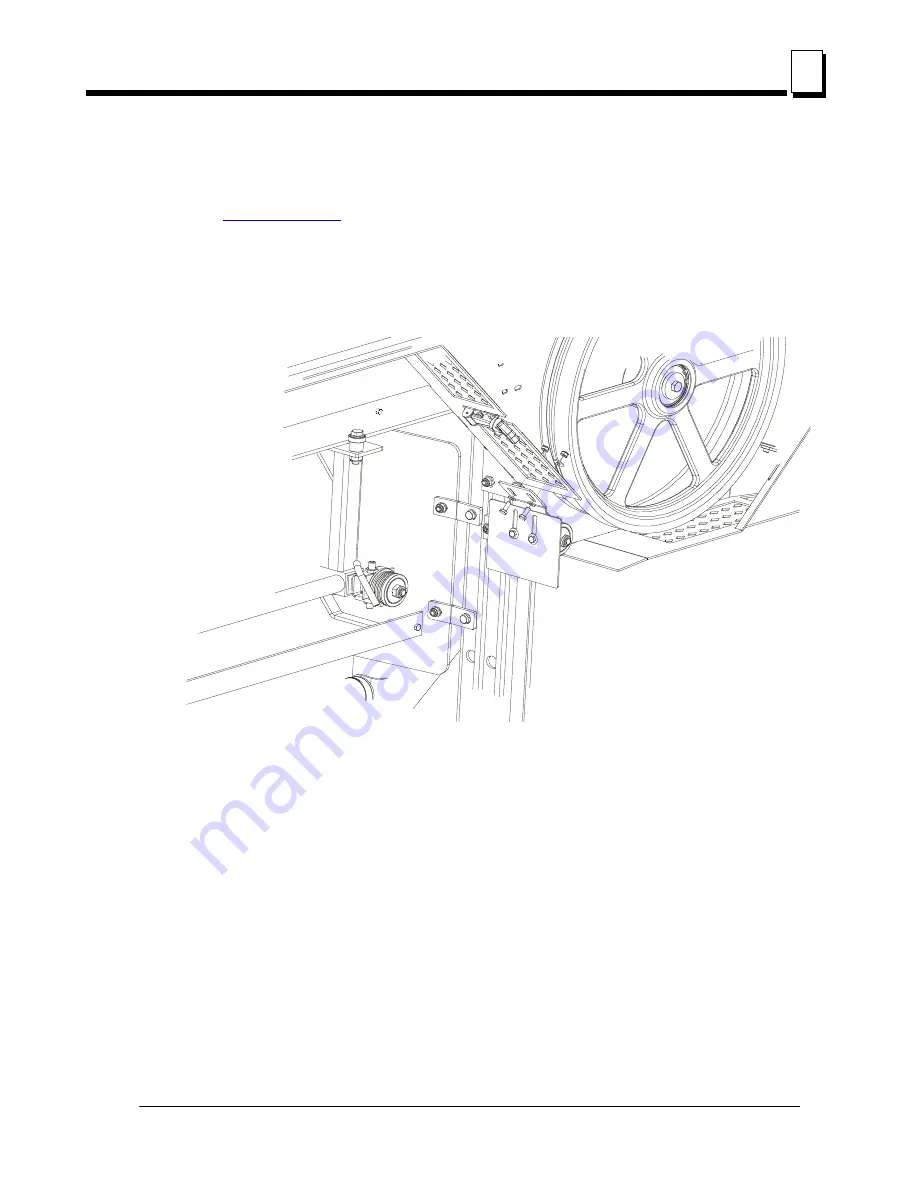
Bolt the blade guide guard so that its bottom edge is about 5 mm above the blade.

See Figure 3-7. 

FIG. 3-7

Содержание LT15SA

Страница 1: ......

Страница 2: ......

Страница 3: ...ation Maintenance Manual LT15SA rev A1 02 Safety is our 1 concern Read and understand all safety information and instructions before operating setting up or maintaining this machine Form 794 This is t...

Страница 4: ...sawmill Before Operation Keep Persons Away Keep Hands Away Use Proper Maintenance Procedures Keep Safety Labels In Good Condition 1 7 Belt Sizes 1 13 1 8 Blade Sizes 1 13 1 9 Cutting Capacity 1 14 1 1...

Страница 5: ...d Operation 3 23 3 13 Cutting The Log 3 24 3 14 Edging 3 25 3 15 Blade Height Scale 3 25 3 16 Water Lube Operation 3 27 3 17 Transporting the Sawmill 3 28 SECTION 4 MAINTENANCE 4 1 4 1 Wear Life 4 1 4...

Страница 6: ...acing 6 13 6 10 Horizontal Tilt Adjustment 6 14 6 11 Side Supports 6 14 6 12 Blade Height Scale Adjustment 6 15 6 13 Motor Drive Belt Adjustment 6 17 6 14 Safety Handle Linkage Adjustment 6 18 6 15 Tr...

Страница 7: ...1 Major Revision Code 00 Minor Revision Type Revision Number Code S3 Bed Frame Type Company Identification Number 456 Wood Mizer Indiana Weight Class A Under 1300 kg B 1301 1800 kg C 1801 2200 kg D 22...

Страница 8: ...perator s Manual before operating the sawmill Take notice of all safety warnings throughout this manual and those posted on the machine Keep this manual with this machine at all times regardless of ow...

Страница 9: ...ice Representative Please have your machine identification number and your customer number ready when you call The Service Representative can help you with questions about the operation and maintenanc...

Страница 10: ...WITZERLAND Stefan Wespi Maschinen u Ger te Spezialarbeiten GmbH Eichistra e 4 6353 Weggis Tel 41 0 41 3900312 GSM 41 0 79 9643594 info mobilsaegen ch RUSSIA Dariusz Miko ajewski OOO WOOD MIZER INDUSTR...

Страница 11: ...Kerestecilik San ve Tic Ltd Sti Adana Keresteciler Sitesi 191 sk No 41 ADANA Tel 90 322 346 15 86 Fax 90 322 345 17 07 GSM 90 533 363 18 44 e mail info erkaahsap com tr FINLAND Howard Blackbourn Oy Fa...

Страница 12: ...55312 2042 e mail Info dragtbosbouw nl Subagent ROMANIA M Echert S C Echert Comprod s r l Str Schitului Nr 6 Apt 7 etajul 1 725 70 Vatra Dornei Romania Tel Fax 40 230 374 235 Tel 40 740 35 35 74 Regi...

Страница 13: ...Also read any additional manufacturer s manuals and observe any applicable safety instructions including dangers warnings and cautions Always be sure that all safety decals are clean and readable Rep...

Страница 14: ...ding and unloading the sawmill Failure to do so may result in serious injury or death 1 4 Sawmill Operation IMPORTANT The sawmill is intended for sawing wood only See Section Cutting Capacity for log...

Страница 15: ...forward so the log does not hit it Failure to do so may result in machine damage CAUTION Do not try to force the saw head beyond its upper and lower travel limits Damage to the up down system may resu...

Страница 16: ...ne NOTE ONLY safety instructions regarding personal injury are listed in this section Caution statements regarding only equipment damage appear where applicable throughout the manual Observe Safety In...

Страница 17: ...rsons away from area when coiling carrying or changing a blade Failure to do so may result in serious injury WARNING Always wear eye ear respiration and foot protection when operating or servicing the...

Страница 18: ...do so will result in serious injury Keep Hands Away DANGER Always shut off the blade motor before changing the blade Failure to do so will result in serious injury DANGER Motor components can become v...

Страница 19: ...t covers closed and securely fastened during sawmill operation WARNING Consider all electrical circuits energized and dangerous WARNING Disconnect and lock out power supply before servicing the sawmil...

Страница 20: ...Keep Safety Labels In Good Condition IMPORTANT Always be sure that all safety decals are clean and readable Replace all damaged safety decals to prevent personal injury or damage to the equipment Con...

Страница 21: ...tension Turning the bolt clockwise will increase the blade tension and turning the bolt counterclockwise will decrease the tension 099221 CAUTION Keep all persons a safe distance away from work area w...

Страница 22: ...9 Safety 096319 CAUTION Disconnect power supply before opening the box 096321 Blade movement direction S12004G CAUTION Always wear safety goggles when operating the sawmill S12005G CAUTION Always wear...

Страница 23: ...CAUTION Always wear safety boots when operating the sawmill 501467 Lubrication Point P11789 Aligning the blade on the wheels 099226 Power feed system engagement 510643 Setting the blade tension indica...

Страница 24: ...Safety P85070 CE safety certification 099401 Russian safety certification S20097F 2925 r p m motor rotation direction P85066 Blade positioning 501477 Safety handle The blade is stopped when the handle...

Страница 25: ...ulley Belts B57 1 1 To insure proper blade tracking use Goodyear Dayco Super II or Browning belts only P04185 TABLE 1 2 Engine Motor Size Recommended Blade For Sawing 3 Softwood Hardwood Frozen or Har...

Страница 26: ...Each additional bed frame segment adds approximately 195 cm 6 5 to length capacity LT15SA S3 70 cm 5 4 m LT15SA S4 70 cm 7 3 m TABLE 1 4 Engine Motor Type Manufacturer Model Number Specifications 5 5...

Страница 27: ...missionlevelsandarenotnecessarily safeworkinglevels Whilstthereis a correlation between the emission and exposure levels this cannot be used reliably to determine whether or not further precautions ar...

Страница 28: ...are value of weighted acceleration to which the whole operator s body is subjected does not exceed 0 5 m s2 Airflow 1200 m3 h 3937ft3 h Inlet diameter 100 mm 5 9 Motor power 1 5 kW Number of sacks 1 p...

Страница 29: ...Safety Overall Dimensions Safety doc022219 1 17 1 1 13 Overall Dimensions See Figure 1 2 The overall dimensions of the LT15SA sawmills are shown below FIG 1 1 2151 2051 967 2280 1704 10_002e...

Страница 30: ...ty 1 14 Components See Figure 1 3 The major components of the Wood Mizer LT15SA are shown below FIG 1 2 10_001_G Water Tank Blade Tensioner Up Down Crank Handle Sawmill Frame Log Clamp Blade Guide Arm...

Страница 31: ...c022219 1 19 1 See Figure 1 4 The major components of the Wood Mizer LT15 are shown below FIG 1 3 Water Tank Blade Tensioner Up Down Crank Handle Sawmill Frame Log Clamp Blade Guide Arm Handle Engine...

Страница 32: ...ting Parts Fig Wood Mizer No Description Qty LT15SA S3 LT15SA S4 LT15SA EC 094514 LT15 Bed Section Complete 1 95 m 3 4 3 085981 1 Thick Spacer Washer 6 8 085982 1 Log Side Support Complete 6 8 085994...

Страница 33: ...50 1 Track Rail Zinc plated Short 2 2 095490 1 Auxiliary Bed Rail 1 1 100903 1 Sawdust Chute 1 1 500844 1 Bed Extension Tube Painted 2 2 502725 1 Feed Rope Mount Front Bracket 1 1 502726 1 Feed Rope M...

Страница 34: ...03768 1 Guide Upright 1 Table 2 Wood Mizer No Description Qty LT15SA E C Sample designations of fasteners F81003 17 M10x35 Bolt 1 F81030 2 M5 Nut 2 F81000 7 M5x25 Bolt 2 F81001 7 M6x12 Bolt 2 2 F81054...

Страница 35: ...F81053 1 Washer 6 4 Flat Zinc 2 2 095919 Cap A 50x30 Black 2 097480 Pipe Cap 40x40x 3 4 6 F81056 1 13 Flat Washer 2 28 F81034 1 M12 Hex Nut 2 2 F81034 2 M12 Hex Nylon Lock Nut 14 F81004 38 M12x120 Bol...

Страница 36: ...WMILL ASSEMBLY 2 2 Unpacking the Sawmill See Figure 2 1 1 Cut the bands holding the components together 2 Remove frame parts from the pallet 3 Remove up down crank from the saw head slide on the up do...

Страница 37: ...head Open the box with the sawmill s equipment 2 3 Bed Frame Assembly IMPORTANT With all screw joints without spring lock washer or lock nylon nut use the LOCTITE 243 blue of average durability for s...

Страница 38: ...e Figure 2 3 2 In case of sawmills with non adjustable legs Mount four or six legs to each bed section Use two hex head bolts and lock nuts to secure each leg to the bed section FIG 2 3 150158b M10x75...

Страница 39: ...ls adjustable legs Mount four or six leg brackets to each bed section Use two hex head bolts and lock nuts to secure each leg bracket to the bed section Be sure the nut on the bracket faces up Thread...

Страница 40: ...y the frame sections end to end so the track portion of each section is on the same side Slide the sections together and secure with four hex head bolts and nylon lock nuts FIG 2 5 150160a M10x120 Bol...

Страница 41: ...ame See the figure above Secure each strap to the track rail with two hex head bolts Tighten the track rail mounting nuts 6 Mount a bed extension to the front and the rear ends of the bed frame FIG 2...

Страница 42: ...head bolts and nylon lock nuts 8 Install the log side supports as shown in Figure 2 8 Tighten the nuts so that the side supports can be moved with little resistance Adjust the side supports See Secti...

Страница 43: ...Figure 2 8 2 4 Frame Leg Adjustment 1 Place a foot plate under each bed leg 2 Using an appropriate wrench adjust each leg so that the nut is approximately 25mm below the top of the bed tube FIG 2 8 15...

Страница 44: ...Saw Head Assembly 1 Using a forklift truck or a winch with lifting capacity of minimum 500 kg carefully lift the saw head and set it aside Attach the winch hook to the bracket on the saw head WARNING...

Страница 45: ...ad rollers onto the bed frame track Keep the saw head square to the bed to avoid jamming the track rollers WARNING When setting the saw head on the bed frame use extreme care and keep all persons at a...

Страница 46: ...gure 2 11 NOTE Before installing the track cover and the remaining felt wipers soak the felt strips with lubricating fluid e g mineral oil 3 Assemble the sawdust chute 100903 1 FIG 2 11 10_054_A M8x12...

Страница 47: ...15doc022219 2 16 2 See Figure 2 12 4 Install the operator guard See Figure 2 13 FIG 2 12 FIG 2 13 10_052c 100903 1 M8x16 Bolt 8 4 Washer 10_055a M10x50 Bolt M8x16 Bolt M8x25 Bolt 8 4 Washer Guard 0938...

Страница 48: ...Head Assembly 2 2 17 15doc022219 SAWMILL ASSEMBLY 5 Install the blade guides See Figure 2 14 6 Install the power cord bracket FIG 2 14 Screw M10x1x20 7 Blade Guide 094682 M10x1x25 Bolt Nut M10x1 Thin...

Страница 49: ...acket 1 to the bed frame section tube using two bolts 2 four washers 3 and two nuts 4 in the place shown below Insert the ramp assembly 5 into the ramp bracket 1 FIG 2 15 1 See the Parts List for deta...

Страница 50: ...SAWMILL ASSEMBLY Log Loading Ramp Option 2 2 19 15doc022219 SAWMILL ASSEMBLY See Figure 2 16 FIG 2 16 1 2 3 3 4 150232a 5...

Страница 51: ...Under roof the sawmill should always be operated with the sawdust collection system The sawmill cannot be operated outdoors when it is raining snowing and in case of rain snow the sawmill must be sto...

Страница 52: ...A Ground Fault Interrupter GFI be used 3 1 2 Sawmills with gas blade drive engine Set up the sawmill on firm level ground and level the sawmill Secure the sawmill to the ground to prevent moving durin...

Страница 53: ...ved or reassembled If sawing problems occur and misalignment is suspected see See 6 1 for complete alignment instructions 1 Adjust the frame legs so the sawmill appears level If sawmill is on soft gro...

Страница 54: ...stance from the bed rail to the bottom of the blade near the inside fixed blade guide 8 Measure the distance from the bed rail to the bottom of the blade near the outside movable blade guide See Figur...

Страница 55: ...own 9 Make sure the entire face of each slide pad makes contact with the mast Use the adjustment nuts shown below to adjust the slide pads if necessary FIG 3 2 150116D Roller Bracket Mounting Bolt 4 S...

Страница 56: ...Check the vertical alignment of each blade wheel using the blade guide alignment tool Attach the tool to the blade near the outer blade guide Be sure the tool does not rest on a tooth or burr and is...

Страница 57: ...inner blade guide Measure from the tool to the bed rail at both ends of the tool If the measurements at the front and rear ends of the tool differ by more than 1 16 1 5 mm adjust the vertical tilt of...

Страница 58: ...ing between each blade guide roller flange and the back of the blade See Section 6 9 12 Adjust the horizontal angle of the blade guides See Section 6 10 13 Adjust the blade deflection See Section 6 7...

Страница 59: ...e the distance from the bottom edge on a down set tooth of the blade to the top of the bed rail Then stick the blade height scale on the mounting bracket so that it indicates the true distance from th...

Страница 60: ...in serious injury and machine damage 3 2 Replacing The Blade DANGER Always disengage the blade and shut off the sawmill motor before changing the blade Disconnect the power supply using the main switc...

Страница 61: ...on the wheels so the gullet is 1 8 3 0 mm out from the front edge of the wheel Position 1 1 2 wide blades on the wheels so the gullet is 3 16 4 5 mm out from the front edge of the wheel Close the blad...

Страница 62: ...f the blade 2 Start the motor for a moment until the blade positions itself on the wheels WARNING Do not spin the blade wheels by hand Spinning the blade wheels by hand may result in serious injury 3...

Страница 63: ...he blade is the correct distance from the front edge of the wheel 4 Adjust the blade tension if necessary to compensate for any changes that may have occurred while adjusting the cant control 5 Close...

Страница 64: ...the blade before starting the engine or motor Failure to do so will result in serious injury WARNING Always wear eye ear respiration safety clothing and foot protection when operating the sawmill Fai...

Страница 65: ...the loading side of the sawmill frame CAUTION Be sure the log clamps are all the way down before loading a log onto the bed Failure to do so may result in machine damage 3 Raise the side supports on t...

Страница 66: ...ps use boards for ramps or use log loading equipment to load the log on the sawmill bed To Turn Logs 1 Use a cant hook to spin the log against the side supports until it is turned the way you want it...

Страница 67: ...re not back the clamps off slightly and push the side supports down until they are positioned below the height of your last cut on a given side of the log To Level A Tapered Log Use shims or the optio...

Страница 68: ...Up Down Operation 1 Install a blade if needed and check for correct blade tension See Section 3 3 Set the cutting head to the desired height The blade height scale shows the height of the blade above...

Страница 69: ...NING DO NOT try to force the carriage above the 27 68 cm mark or below the 1 2 54 cm mark Damage to the up down system may result 3 9 Up Down Operation Option with Electrical Up Down System 1 Install...

Страница 70: ...system may result 3 10 Blade Guide Arm Operation 1 Look down the length of the log to see its maximum width The outer blade guide roller should be adjusted to clear the widest section of the log by le...

Страница 71: ...otection when operating the sawmill Failure to do so may result in serious injury Be sure the blade housing cover is in place and secured before starting the engine or motor Use the rubber latches to...

Страница 72: ...p button located on the electric box To engage the blade perform the following steps sawmills with gas blade drive engine 1 Clear any loose objects from the area of the blade motor and drive belt 2 Ma...

Страница 73: ...eed rate as desired Maximum feed rate varies with width and hardness of the wood Over feeding results in blade and drive belt wear CAUTION Be sure to stop the blade when returning the cutting head Thi...

Страница 74: ...end of the log slow down the feed rate When the teeth exit the end of the log release the safety handle on the control box Remove the slab that you have just cut from the log 7 Use the feed crank to r...

Страница 75: ...ew of the widest boards 5 Loosen the clamps and turn the edged boards over to edge the other side 6 Repeat steps 2 4 7 Loosen the clamps and remove the boards that have good clean edges on both sides...

Страница 76: ...cluded but actual board thickness will vary slightly depending on blade thickness and tooth set To choose which scale to use determine what finished thickness you want to end up with The Grade Hardwoo...

Страница 77: ...r Lube System keeps the blade clean Water flows from a 5 liter bottle through a hose to the blade guide where the blade enters the log A valve in the bottle cap controls the amount of water flow See F...

Страница 78: ...re removing the blade engage blade drive Let the blade spin with water running on it for about 15 seconds This will clean the blade of sap buildup Wipe the blade dry with a rag before storing or sharp...

Страница 79: ...he bed of the truck 6 With a person positioned on either side of the cutting head disengage the travel lock pin Push the cutting head up the bed frame and engage the travel lock pin in the end of the...

Страница 80: ...ble 4 1 This chart lists estimated life expectancy of common replacement parts if proper maintenance and operation procedures are followed Due to the many variables which exist during sawmill operatio...

Страница 81: ...grade sand paper Lubricate the mast with motor oil or automatic transmission fluid e g Dextron II or Dextron III CAUTION Never use grease on the mast rails as it will collect sawdust 4 5 Miscellaneous...

Страница 82: ...wn chain tension as needed Measure chain tension with the saw head all the way to the top of the vertical mast Secure the saw head with a chain at the top or shim it underneath Find the chain adjustin...

Страница 83: ...irt Replace any damaged or unreadable decals immediately Order decals from your Customer Service Representative 4 9 Safety Devices Inspection CE version only Sawmill with electric blade drive motor Sa...

Страница 84: ...is released Press and hold the safety handle Turn on the blade motor Release the safety handle The blade motor should be stopped Press and hold the safety handle The blade motor should remain stopped...

Страница 85: ...inspection Safety handle and its circuit inspection Blade cover safety switches and its circuit inspection 1 E STOP button and its circuit inspection Press and hold the safety handle Start the engine...

Страница 86: ...safety handle The engine should be stopped 3 Blade cover safety switch and its circuits inspection Press and hold the safety handle Start the engine Open blade housing cover The engine should be stopp...

Страница 87: ...BLADE CHANGE Check Blade Guide Roller Performance SEE SECTION 4 2 Remove Excess Sawdust From Blade Wheel Housings And Sawdust Chute SEE SECTION 4 2 EVERY 8 HOURS Clean And Lubricate Track SEE SECTION...

Страница 88: ...1 2 30doc022219...

Страница 89: ...mast See Section4 4 Check blade wheel belts for wear See Section4 6 Lubricate blade tensioner screw See Section4 5 WOOD MIZER LT15SA LT15 MAINTENANCE LOG PROCEDURE MANUAL REFERENCE TOTAL HOURS OF OPER...

Страница 90: ...mast See Section4 4 Check blade wheel belts for wear See Section4 6 Lubricate blade tensioner screw See Section4 5 WOOD MIZER LT15SA LT15 MAINTENANCE LOG PROCEDURE MANUAL REFERENCE TOTAL HOURS OF OPE...

Страница 91: ...n4 4 Check blade wheel belts for wear See Section4 6 Lubricate blade tensioner screw See Section4 5 WOOD MIZER LT15SA LT15 MAINTENANCE LOG PROCEDURE MANUAL REFERENCE TOTAL HOURS OF OPERATION FILL IN T...

Страница 92: ...1 4 30doc022219...

Страница 93: ...s being sharpened completely See Sharpener Manual Blades Break Prematurely Rubber belts on blade wheels worn to a point that blade contacts metal pulley look for shiny spots on edge of wheels Change b...

Страница 94: ...st slide pads are not adjusted properly the entire surface of the pad should touch the mast Adjust pads Lumber Is Not Square Sawdust or bark between cant and bed rails Remove particles Tooth set probl...

Страница 95: ...p information 6 2 Preparing The Sawmill For Alignment Before performing the following alignment procedures setup the mill on firm level ground String the bed and adjust the legs so the frame is level...

Страница 96: ...xt section in this manual 6 4 Blade Wheel Alignment The blade wheels should be adjusted so they are level in the vertical and horizontal planes If the blade wheels are tilted up or down the blade will...

Страница 97: ...e first bed rail Measure from the bottom of the tool to the top surface of the bed rail 3 Move the saw carriage so the rear of the tool is positioned over the bed rail Again measure from the bottom of...

Страница 98: ...ust the blade wheel as necessary until the front and rear of the tool are the same distance from the bed rail within 1 16 1 5 mm 6 Remove the tool from the blade and re attach it near the outer blade...

Страница 99: ...crew Tighten the top and bottom jam nuts 8 Re check the vertical tilt of the idle side blade wheel Readjust if necessary 9 Check the position of the blade on the idle side blade wheel See Figure 6 5 T...

Страница 100: ...too far back on the wheel turn the cant control clockwise 10 Check the position of the blade on the drive side blade wheel The blade should be positioned on the wheel as described for the idle side b...

Страница 101: ...ill Alignment 15doc022219 6 7 6 adjustment screw to move blade in on wheel Tighten the jam nut 11 Adjust the blade vibration damper screw Distance from the screw to the blade should be about 1 mm See...

Страница 102: ...justment screws marked with blue arrows in the figure above to adjust the arm up until the slide pad touches the saw head brace tube Tighten the jam nuts 3 Adjust the blade guide arm in all the way to...

Страница 103: ...ward the rear of the sawmill loosen jam nuts on the front outside screw and the rear inside screw Turn the screws counterclockwise one full turn and tighten the jam nuts Loosen the jam nuts on the fro...

Страница 104: ...m the following steps to achieve proper blade deflection with the blade guides 1 Raise the carriage until the blade is 15 375 mm above a bed rail Measure the actual distance with a tape from the top o...

Страница 105: ...ol on the blade Position the tool close to a blade guide roller Be sure the tool does not rest on a tooth or burr and is lying flat on the blade See Figure 6 12 3 Measure the distance from the bed rai...

Страница 106: ...urements taken 9 Move the tool close to the other blade guide and repeat the previous steps NOTE If major adjustments to blade guide tilt were made remeasure the distance between the blade and the bed...

Страница 107: ...ide flange is approximately 1 16 1 8 1 5 3 0 mm from the back of the blade 2 Loosen one side and one top set screw shown on the figure below Tap the blade guide forward or backward until properly posi...

Страница 108: ...r end of the tool A 5 The roller should be parallel to the blade A B or tilted slightly to the left A B 1 4 6 mm Use the side set screws to adjust the horizontal tilt of the roller 6 Repeat Steps 3 7...

Страница 109: ...h a square on the board 5 The side support should be 90 to the bed rails Turn the adjustment bolt counterclockwise to tilt the top of the side support forward 6 Repeat for the remaining side supports...

Страница 110: ...the scale bracket mounting bolt and adjust the bracket until the indicator is aligned with the correct mark on the scale Retighten the nut on the bracket mounting bolt Quarter Inch Scale Option 1 The...

Страница 111: ...the nuts on the bracket mounting bolts For example if the measurement from blade to bed rail was 14 3 4 375 mm make sure the indicator reads 14 3 4 375 mm on the scale 6 13 Motor Drive Belt Adjustmen...

Страница 112: ...ll Alignment motor Tighten the four motor mounting bolts 6 14 Safety Handle Linkage Adjustment See Figure 6 20 Use the adjustment nuts to adjust linkage tension so the blade stops during FIG 6 19 Moto...

Страница 113: ...econds after the safety handle is released 6 15 Track Roller Distance Adjustment Using the screw 1 adjust the distance between the track roller 2 and the track rail 3 so that the vertical mast can mov...

Страница 114: ...Sawmill Alignment Track Roller Distance Adjustment 6 6 20 15doc022219 Sawmill Alignment See Figure 6 21 FIG 6 21 0 5 mm 1 2 3...

Страница 115: ...til the run in operation of the friction surfaces has been completed After replacing the rotor run in armature plates and flanges have an increased initial rate of wear Checking the rotor thickness DA...

Страница 116: ...adjust the air gap to sL rated Brake type sL rated 0 1mm 0 05mm sL max Service brake Max adjustment permissible wear Rotor thickness Excess of the adjuster nut hEmax mm min 1 mm max mm INTORQ BFK458 2...

Страница 117: ...th declare that Designation of the machine SAWMILL Model LT15 TYPE No of manufacturer Is in conformity with the following EC directives EC Machinery Directive 2006 42 EC EC Electromagnetic Compatibili...

Отзывы: