


Adjustments
Cutting Head #3
Adjustments
MO01doc091902
3-8
3
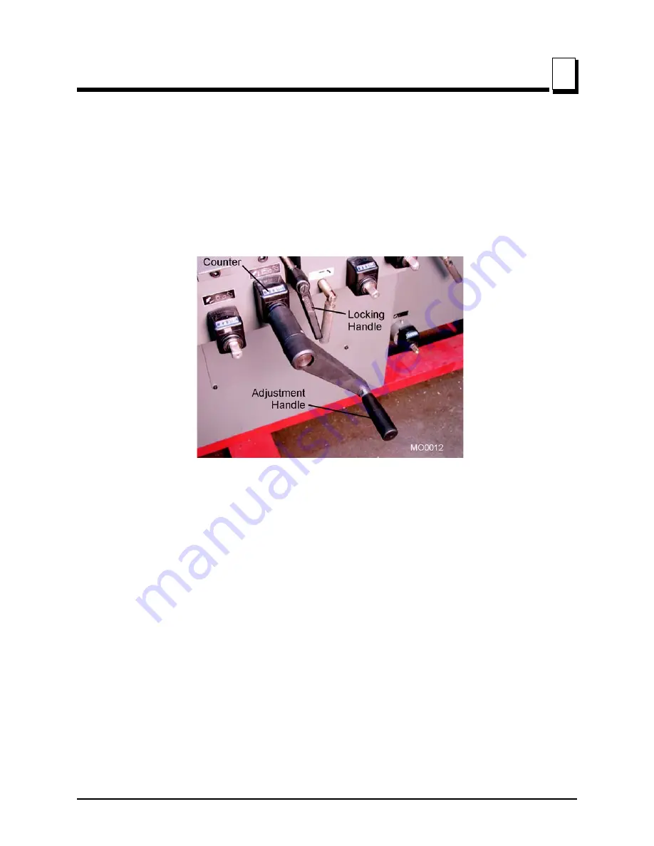
Vertical Adjustment
Using a finished sample of moulding as a guide, adjust cutting head #3 up or down as
necessary.
See Figure 3-8.
Loosen the locking handle and use the supplied wrench handle to turn
the adjustment shaft clockwise to raise the blade, counterclockwise to lower the blade.
Retighten the locking handle and reset the counter to zero.
NOTE:
When lowering the blade, lower it further than
desired then back up to remove slack from the adjusting
screw.
FIG. 3-8
Содержание 4015X5
Страница 5: ...About This Manual MO01doc091902 v M4015X5 MOULDER MO0001 ...
Страница 51: ...Electrical Information Electrical Schematics Electrical Information MO01doc091902 8 2 8 FIG 8 1 PAGE 2 OF 3 ...
Страница 52: ...Electrical Information Electrical Schematics 8 8 3 MO01doc091902 Electrical Information FIG 8 1 PAGE 3 OF 3 ...