


Diagram 4.4
-
2
10vi
5V
7.5V
2.5V
4~20mA Current Output:
the current output
control is commonly used at linear control
system, like as electrical valve control applied
for oil/liquid control system.
The I
-
out (CH4) wiring refers to Diagram 4.4
-
2.
4.5
PWM (Pulse Width Modulation) Output
CH
-
6 PWM 5V Output – JP6
The CH
-
6 default is PWM 5V output with certain duty
-
cycle and operating in push
-
pull mode.
Once, the jumper change to O.C. mode the output voltage will refer to the connected device
internal voltage, the limited voltage is 30V.
CH
-
7 PWM 10V Output – JP8
The CH
-
7 default is PWM 10V output with certain duty
-
cycle and operating in push
-
pull
mode. Once, the jumper change to O.C. mode the output voltage will refer to the connected
device internal voltage, the limited voltage is 30V.
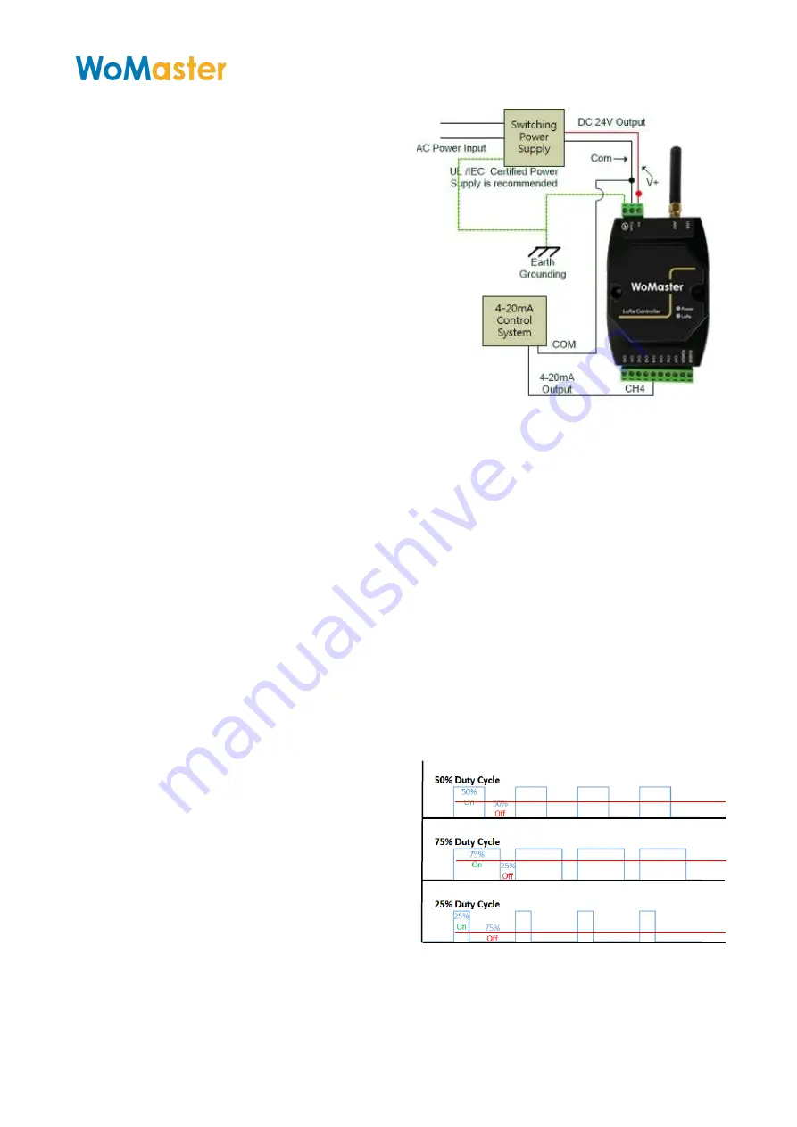
Theory of PWM Duty
-
Cycle Control
The PWM control uses constant voltage as
output, and adjusts the duty cycle to
control the PWM dimmer output.
In the diagram 4.5
-
1, the output voltage is
10V, modulate the On/Off duty cycle, and the
end control device internal get voltage will be
“Full
-
Volt x Duty Cycle %”.
Example: Full _Output = 10V
50% Duty Cycle, the End Control Device
measured 5V, 75% get 7.5V and so on.


