background image


649-015 

P2008  © Firma WJG, Braunschweig. Nachdruck oder Vervielfältigung  nur mit ausdrücklicher Genehmigung 

 
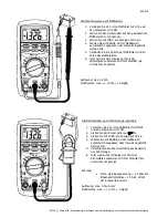
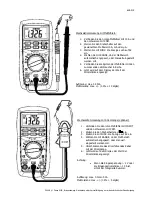
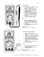
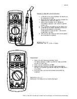
Operation: 


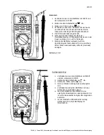
Before you perform any measurement insert the three batteries. Release the screw of the battery 

compartment on the backside. Switch the device off every time you exchange the batteries.   


Plug the sensors in but pay attention which terminals you have to use. This depends on the type of 

measurement you want to do. (For details see „The procedures of Measurement“) 


Switch the device with ON/OFF on. 


Use the rotary switch and the button RANGE to adjust the testing range. 


Precede the measurement as described under „The procedures of Measurement”.  


As the case may be choose a hold-function either DATA H. or MAXH. The measurement is adjourned 

when the button is pressed or a maximal value occurred. To continue the measurement presses the 

button again. 


If you can not read the values clearly turn on the backlight b pressing   for more than 2 seconds. It will 

be active for the next 15 seconds.  


After finishing the measurements switch the device with ON/OFF off again.      


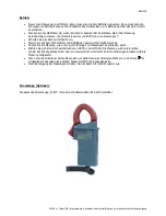
Clamp Meter (Optional): 


The suitable clamp meter „M-97z“ is available under the item-number 649-018. 


Содержание M-82Pro

Страница 1: ...automatische Meßbereichsauswahl und Data Hold Funktion Mißt Stromstärke Spannung Temparatur und elektrischen Widerstand Mißt die Kapazität eines Kondensators Es kann Dioden und Transistoren testen und Durchgangsprüfungen vornehmen Meßfühler Temperatursensor Adapter für Transistoren und Aufsteller sind enthalten Sicherheitshinweise Überprüfen Sie vor Inbetriebnahme das Gerät auf Beschädigungen soll...

Страница 2: ...sprüfung Beim Diodentest wird die Vorwärtsspannung Durchlaßspannung einer Diode in V angezeigt Bei der Durchgangsprüfung ertönt bei Widerständen 50 Ω ein akustisches Signal Zwischen beiden Funktionen kann mit FUNC umgeschaltet werden hFE Zeigt die Durchlassstromverstärkung eines Transistors an TEMP Temperaturmessung Die Temperatur wird in C oder F angezeigt Zwischen beiden Einheiten kann mit FUNC ...

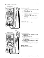
Страница 3: ...Meßobjektes 6 Jetzt wird auf dem Display der Wert der Spannung zusammen mit ihrer Polarität als Vorzeichen angezeigt Auflösung max 0 1mV Meßtoleranz max 0 7 2 digits Wechselspannungsmessung 1 Verbinden Sie den roten Meßfühler mit INPUT und den schwarzen mit COM 2 Stellen Sie den Drehschalter auf V ein 3 Stellen Sie mit FUNC die Anzeige auf AC ein 4 Wählen Sie mit RANGE ob der Meßbereich automatisc...

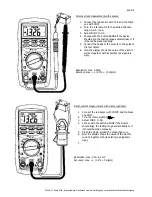
Страница 4: ...Stromstärke zusammen mit ihrer Polarität als Vorzeichen angezeigt Auflösung max 0 001A Meßtoleranz max 2 0 10 digits Gleichstrommessung mit Stromzange optional 1 Verbinden Sie den roten Meßfühler mit INPUT und den schwarzen mit COM 2 Stellen Sie den Drehschalter auf ein 3 Stellen Sie mit FUNC die Anzeige auf DC ein 4 Wählen Sie mit RANGE ob der Meßbereich automatisch angepasst oder manuell eingest...

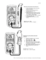
Страница 5: ...r in Reihe 6 Jetzt wird auf dem Display der Wert der Stromstärke angezeigt Auflösung max 0 001A Meßtoleranz max 3 0 10 digits Wechselstrommessung mit Stromzange optional 1 Verbinden Sie den roten Meßfühler mit INPUT und den schwarzen mit COM 2 Stellen Sie den Drehschalter auf ein 3 Stellen Sie mit FUNC die Anzeige auf AC ein 4 Wählen Sie mit RANGE ob der Meßbereich automatisch angepasst oder manue...

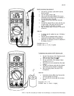
Страница 6: ... Stabilisierungszeit Sollte ein manuell eingestellter Meßbereich überschritten werden zeigt das Display OL Overload an Sollte der Meßstrom unterbrochen sein zeigt das Display eine 1 an Auflösung max 1 Ω Meßtoleranz max 1 0 5 digits Temperaturmessung mit Thermoelement 1 Verbinden Sie das rote Kabel des Thermoelements mit INPUT und das schwarze mit COM 2 Stellen Sie den Drehschalter auf TEMP ein 3 W...

Страница 7: ...r mit den zwei Enden des Kondensators Polarisierte Kondensatoren müssen mit dem Pol an COM angeschlossen werden 6 Jetzt wird auf dem Display der Wert der Kapazität des Kondensators angezeigt Auflösung max 1 µF Meßtoleranz max 3 0 3 digits Transistortest 1 Stecken Sie den beiliegenden Adapter für die Transistoranschlüsse in INPUT und COM Er funktioniert NPN als auch mit PNP Typen 2 Stellen Sie den ...

Страница 8: ...el zwischen 0 6 V und 3 V betragen 7 Werden die Meßfühler vertauscht wird die Sperrichtung der Diode überprüft d h es darf kein Strom fließen und das Display sollte OL Overload anzeigen Auflösung 1 mV Durchgangsprüfung 1 Verbinden Sie den roten Meßfühler mit INPUT und den schwarzen mit COM 2 Stellen Sie den Drehschalter auf ein 3 Stellen Sie FUNC auch auf ein 4 Die zu prüfenden Leitung muss spannu...

Страница 9: ...ON OFF ein Stellen Sie mit dem Drehschalter und RANGE den gewünschten Meßbereich ein Führen Sie die Messung wie unter Durchführung von Messungen beschrieben durch Wählen Sie ggf Eine der Speicherfuktionen DATA H oder MAXH Die Messung wird unterbrochen sobald der Knopf gedrückt wird oder ein maximaler Wert erreicht ist Bei nochmaligen Drücken wird die Messung fortgesetzt Wenn man das Display schwer...

Страница 10: ...for more then 15 minutes It has an automatic change of measurement range and a data hold function Measures electric current voltage temperature and electric resistance Measures capacitance of a capacitor It performs diode transistor and continuity testing Sensors thermocouple adapter for transistors and positioner are included Security Advices Before using the device please check it for any possib...

Страница 11: ...inuity testing At the diode testing the forward bias through a diode will be shown in V At the continuity testing sounds an acoustic signal if the electric resistance is 50 Ω Toggle between both functions by using FUNC hFE Shows the forward current gain of a transistor TEMP Temperature measurement The temperature will be shown in C or in F Toggle between both units by using FUNC xF Capacitance mea...

Страница 12: ...e poles of the test object 6 Now the display shows the value of the voltage together with its polarity as algebraic sign Resolution max 0 1mV Accuracy max 0 7 2 digits AC voltage measurement 1 Connect the red sensor with INPUT and the black one with COM 2 Turn the rotary switch to V 3 Adjust FUNC to AC 4 Choose with the button RANGE if the device should align the testing range automatically or if ...

Страница 13: ...he poles of the test object 6 Now the display shows the value of the electric current together with its polarity as algebraic sign Resolution max 0 001A Accuracy max 2 0 10 digits Direct current measurement with clamp optional 1 Connect the red sensor with INPUT and the black one COM 2 Turn the rotary switch to 3 Adjust FUNC to DC 4 Choose with the button RANGE if the device should align the testi...

Страница 14: ...e manually 5 Connect the heads of the sensors to the load to be measured in series 6 Now the display shows the value of the current Resolution max 0 001A Accuracy max 3 0 10 digits Alternating current measurement with clamp optional 1 Connect the red sensor with 10 A and the black one with COM 2 Turn the rotary switch to 3 Adjust FUNC to AC 4 Choose with the button RANGE if the device should align...

Страница 15: ...ectric resistances over 1 MΩ takes to stabilize Should a manual adjusted testing range be exceeded the display shows OL Overload Should the measurement current be adjourned the display shows 1 Resolution max 1 Ω Accuracy max 1 0 5 digits Temperature measurement witht thermocouple 1 Connect the red wire of the thermocouple to INPUT and the black one to COM 2 Turn the rotary switch to TEMP 3 Choose ...

Страница 16: ...ct the heads of the sensor with the two ends of the capacitor Polarized capacitors must connect to COM with their negative electrode 6 Now the display shows the value of the capacitance of the capacitor Resolution max 1 µF Accuracy max 3 0 3 digits Transistor Testing 1 Connect the enclosed adapter for transistor leads to INPUT and COM It works either for NPN or PNP types 2 Turn the rotary switch t...

Страница 17: ...the sensors are interchanged you can check the reverse biasing of the diode This means thee should be no electricity at all and the display should show Overload Resolution 1 mV Continuity testing 1 Connect the red sensor with INPUT and the black one with COM 2 Turn the rotary switch to 3 Adjust FUNC also to 4 Die zu prüfenden Leitung muss spannungslos sein 5 Connect the two sensors to two differen...

Страница 18: ...the device with ON OFF on Use the rotary switch and the button RANGE to adjust the testing range Precede the measurement as described under The procedures of Measurement As the case may be choose a hold function either DATA H or MAXH The measurement is adjourned when the button is pressed or a maximal value occurred To continue the measurement presses the button again If you can not read the value...

Отзывы: