


Electrical installation
INTORQ | BA 14.0197 | 04/2016
31
5
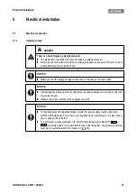
Electrical installation
5.1
Electrical connection
5.1.1
Important notes
DANGER
There is a risk of injury by electrical shock!
❚
The electrical connections must only be made by skilled personnel!
❚
Only carry out connection work when no voltage is applied (no live parts)! There is a risk of
unintended start-ups or electric shock.
NOTICE
❚
Make sure that the supply voltage corresponds to the data on the name plate.
NOTICE
❚
If an emergency stop is carried out without the required suppressor circuit, the control unit
may be destroyed.
❚
Observe the correct polarity of the suppressor circuit!
NOTICE
❚
To functionally test the individual brake circuits, the power supply must be able to be
switched off individually. For a new over energisation when switching on, it is also neces-
sary to open switches K1/K3.
❚
The protective circuitry contained in the INTORQ switching device BEG-561-
-
(terminals 3 and 4) is not permitted for use in the lift system. The protective circuitry
must be connected parallel to the brake coil (
Содержание WSG-TB.3 series
Страница 29: ......
Страница 30: ......
Страница 31: ......
Страница 33: ......
Страница 37: ......
Страница 38: ......
Страница 39: ......
Страница 43: ......
Страница 44: ......
Страница 45: ......
Страница 46: ......
Страница 47: ......
Страница 95: ...Notes INTORQ BA 14 0197 04 2016 48 Notes...
Страница 144: ...Notes INTORQ BA 14 0210 12 2016 48 Notes...
Страница 145: ...Notes INTORQ BA 14 0210 12 2016 49...
Страница 146: ...Notes INTORQ BA 14 0210 12 2016 50...
Страница 147: ......