


Gearless Lift Machine
WSG-TB
Operating Instructions
Subject to changes without notice ! Subject to changes without notice !
EN
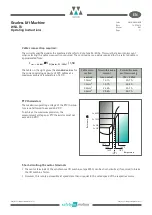
4.2.4. Brake
• Refer also to the operating instructions for the brake.
• The brakes are supplied with DC voltage by the overexcitation rectifiers, which are supplied separately.
• Only the overexcitation rectifiers which are included in our scope of supply are to be used for the brake acti-
vation.
• Repeated switching of the brake magnets during the overexcitation period must be avoided as this will result
in overloading of the brake control unit. Therefore, a minimum brake operating time of approx. 1.5 – 2 s
should be maintained, especially during an inspection or commissioning drive.
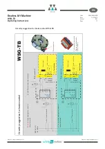
• To reduce the switch-off time, switching can be effected from the DC side. However, switching must also be
performed from the AC side at the same time ! (Wiring with a varistor as shown in the circuitry suggestion
on page 15!)
Note on the use of DC/AC side switching:
AC side switching is recommended for normal operation, since the lift machine is then decelerated in a con-
trolled manner to zero speed and the switching noise of the brake is negligible.
When braking in the event of a breakdown (emergency stop) or during an inspection drive, the switching
should be performed from the DC side, since this ensures a faster braking effect with the car being stopped
earlier. We therefore recommend the use of 2 separate contactors for the brake control circuitry, one of
which switches at the DC side, the other at the AC side.
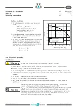
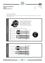
AC side switching
• Low-noise switching of the brake
• No protective measures required for switching
con tact
• Slow application of the brake.
DC side switching
• Noisy switching
• Burn-up protection for switching contact required
(e.g. varistor, free-wheeling diode)
• Fast application of the brake.
~
+
-
Br
-
+
Br
~
Attention:
schematic diagram!
Attention:
schematic diagram!
Monitoring the brakes
• The switching states of the brakes are monitored by means of dust-proof microswitches with gold contacts.
Both the n.c. and the n.o. contact connections are available.
Warning
The microswitches must be evaluated separately for each partial brake to ensure compliance
with the requirements of the type examination.
Gearless Lift Machine
WSG-TB
Operating Instructions
Code
GM.8.004610.FR
Date
14.05.2018
Statut
0.01
Page
13
Subject to changes without notice ! Subject to changes without notice !
EN
Содержание WSG-TB.3 series
Страница 29: ......
Страница 30: ......
Страница 31: ......
Страница 33: ......
Страница 37: ......
Страница 38: ......
Страница 39: ......
Страница 43: ......
Страница 44: ......
Страница 45: ......
Страница 46: ......
Страница 47: ......
Страница 95: ...Notes INTORQ BA 14 0197 04 2016 48 Notes...
Страница 144: ...Notes INTORQ BA 14 0210 12 2016 48 Notes...
Страница 145: ...Notes INTORQ BA 14 0210 12 2016 49...
Страница 146: ...Notes INTORQ BA 14 0210 12 2016 50...
Страница 147: ......