background image


Operation Manual simco

®

 drive


en-30 

4022-D033499 

Revision: 11a 


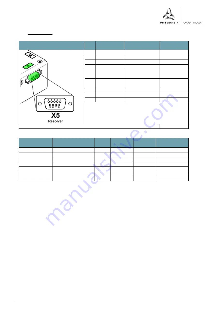
6.4.9  X5: Resolver 


Figure 

Pin 
no. 

Signal name  Function 

Input/output 


COS+ 

Cosine trace S1 

Input 

COS- 

Cosine trace S3 

Input 

SIN+ 

Sine trace S2 

Input 

SIN- 

Sine trace S4 

Input 

REF+ 

Reference trace 
R1 

Output 

REF- 

Reference trace 
R2 

Output 

N.C. 


N.C. 


N.C. 


Plug type on drive amplifier: D-sub 9-pin female 


Connection 

Properties 

Unit 

Minimum 
value 

Nominal 
value 

Maximum 
value 

Reference trace 

Excitation frequency 

kHz 


10 


Output voltage 

Vpk 

5,5 


Output current 

mA 


30 


Sine/cosine 

Input resistance 

kOhm 


100 


Input voltage 

Vpk 


2,5 


Resolution 

Bit 

10 

12 

14 


Содержание SIM2002D-CCSA-CA00-0000-0000

Страница 1: ...4022 D033499 Revision 11a simco drive SIM2002D SIM2010D SIM2015D Operating Manual...

Страница 2: ......

Страница 3: ...a All 11a 25 07 2019 Supplementation picture 6 4 2 6 Service contact If you have questions concerning customer service and repairs please contact our Customer Service department Customer Service WITTE...

Страница 4: ...5 3 Device version IP20 decentral SIM20xxD CC 14 5 3 1 Dimensions IP20 14 5 3 2 Mounting options IP20 14 5 3 3 Demounting IP20 15 5 3 4 Installation space IP20 15 5 3 5 Environmental conditions for vi...

Страница 5: ...3 4 LED P2 Fault status drive 40 7 3 5 LED P3 Status fieldbus 40 7 3 6 LED P4 Fault status fieldbus 41 8 Maintenance and disposal 43 8 1 Maintenance 43 8 2 Repairs 43 8 3 Disposal 43 9 Appendix 43 9...

Страница 6: ...nguage versions are translations of these instructions 1 1 Signal words The following signal words are used to indicate possible hazards prohibitions and important information This signal word indicat...

Страница 7: ...nd accident prevention rules and regulations e g personal safety equipment 2 1 Approvals 2 1 1 CE conformity The drive amplifier was tested in authorized testing laboratories in accordance with the re...

Страница 8: ...Code and any additional local codes For Canada CSA Integral solid state short circuit protection does not provide branch circuit protection Branch circuit protection must be provided in accordance wi...

Страница 9: ...intended usage see Chapter 2 6 Intended use and in a technically flawless and safe state 2 5 Personnel Only qualified specialist staff who have read and understood these instructions may carry out wo...

Страница 10: ...possible using appropriate measures Nonetheless known residual risks must be taken into account for the risk assessment of machines and systems 2 8 1 Prohibited movements Prohibited movements can be...

Страница 11: ...er Designation Designation A Code G Fieldbus type B Article code H Material number customer specific C Intermediate voltage I Protection class D Maximum output current J Permissible ambient temperatur...

Страница 12: ...version CANopen DS402 EtherCAT with CoE PROFINET RT IRT Ethernet IP IO or SERCOS III with FSP Drive are available as communication interfaces The intelligence is reflected in the wide range of encode...

Страница 13: ...n The STO safety function Safe Torque Off is used for safe torque shutdown and to reliably protect drives from restarting The drive amplifier is fitted with a two channel STO function as standard in t...

Страница 14: ...drive amplifiers During installation in a control cabinet sufficient ventilation must be provided The operation of drive amplifiers exposed to condensation is not permitted Installation may only be p...

Страница 15: ...ounting position can be selected 5 2 5 Ventilation cooling IP65 Sufficient convection for cooling of the drive amplifier must be ensured at the installation location To avoid overheating closed instal...

Страница 16: ...Depth without plug mm 84 5 3 2 Mounting options IP20 The drive amplifier may be mounted on a top hat rail of type TS 35 using the integrated top hat clip Alternatively the drive amplifier can be conne...

Страница 17: ...ation space IP20 The central variant of the drive amplifier is designed for installation in the control cabinet 5 3 5 Environmental conditions for vibration shock IP20 The drive amplifier fulfills the...

Страница 18: ...llation the ESD instructions must be observed Systems that are electrically connected must be properly secured so they cannot be switched back on and warning signs must be put up Installation may only...

Страница 19: ...Connection assignments device version IP65 decentral SIM20xxD FC 6 3 1 Overview of plug connections decentral The following illustration shows the arrangement of the plug connections with associated...

Страница 20: ...Operation Manual simco drive en 18 4022 D033499 Revision 11a 6 3 2 Connection diagram IP65 The following illustration shows the principal connection diagram of the drive amplifier...

Страница 21: ...5 5 Output current mA 30 Sine cosine Input resistance kOhm 100 Input voltage Vpk 2 5 5 Resolution Bit 10 12 14 6 3 4 X2 Digital inputs An external reference potential most be connected to supply the d...

Страница 22: ...l Input 6 DATA Data channel inverted Input 7 N C 8 N C Plug type on drive amplifier M12 8 pin female A coded Connection Properties Unit Minimum value Nominal value Maximum value VCC Output voltage V D...

Страница 23: ...nput 3 GND Reference ground 4 N C Plug type on drive amplifier M12 4 pin female A coded Connection Properties Unit Minimum value Nominal value Maximum value TxD RxD Baud rate baud 115200 6 3 8 X6 X7 F...

Страница 24: ...nically isolated from the intermediate voltage pin A B The intermediate voltage pin B is connected inside the device to the housing as a functional ground Figure Pin no Signal name Function Input outp...

Страница 25: ...PHASE_W Motor phase W Output 1 GND Reference ground 2 VCC5 Encoder voltage 5 VDC Output 3 CLOCK Clock signal Output 4 CLOCK Clock signal inverted Output 5 DATA Data signal Input 6 DATA Data signal inv...

Страница 26: ...ector type at cable X1 Fieldbus interface input RJ45 socket RJ45 plug X2 Fieldbus interface output RJ45 socket RJ45 plug X3 Diagnostic interface RS232 RJ12 socket RJ12 plug X4 Encoder interface D Sub...

Страница 27: ...anual simco drive Revision 11a 4022 D033499 en 25 deutsch english fran ais italiano espa ol 6 4 2 Connection diagram IP20 The following illustration shows the principal connection diagram of the drive...

Страница 28: ...hat rail is connected to the control cabinet s functional ground with sufficiently low impedance If the drive amplifier is not sufficiently grounded this may cause radio interference leading to non co...

Страница 29: ...J5 N C J6 N C J7 N C J8 N C Plug type on drive amplifier LAN RJ45 Connection Properties Unit Minimum value Nominal value Maximum value Baud rate kbaud 100 500 1000 6 4 6 X1 X2 Fieldbus interface Ether...

Страница 30: ...ure Pin no Signal Function Input output 1 TxD Transmit Data Output 2 RxD Receive Data Input 3 GND Reference ground 4 N C 5 N C 6 N C Plug type on drive amplifier MOD JACK MJLS 6P6C Connection Properti...

Страница 31: ...D Reference ground Output 2 VCC Encoder power supply Output 3 CLOCK Clock output Output 4 CLOCK Clock output inverted Output 5 DATA Data channel Input 6 DATA Data channel inverted Input 7 A Encoder em...

Страница 32: ...ut 4 SIN Sine trace S4 Input 5 REF Reference trace R1 Output 6 REF Reference trace R2 Output 7 N C 8 N C 9 N C Plug type on drive amplifier D sub 9 pin female Connection Properties Unit Minimum value...

Страница 33: ...tal input 2 Input 3 DIN3 Digital input 3 Input 4 DIN4 Digital input 4 Input 5 GND Reference ground 6 DOUT1 Digital output 1 Output 7 DOUT2 Digital output 2 Output 8 VCC24 Digital output supply Input 9...

Страница 34: ...4 PHASE_V Motor phase V Output 5 PHASE_W Motor phase W Output 6 Chopper External brake resistor 7 Chopper External brake resistor Plug type at cable Phoenix Contact MSTBT 2 5 HC 7 ST Permissible condu...

Страница 35: ...Safe Torque off input Input 3 GND Logic reference ground Input 4 STO GND STO reference ground Input 5 BRAKE Holding brake Output 6 BRAKE Holding brake Output 7 TEMP Motor temperature sensor Input 8 N...

Страница 36: ...are listed in chapter 2 1 2 6 5 2 Fuses on device version central IP20 The power supplies are to be secured with the fuses specified in the table Fuses Logic supply F2 X8 pin 1 2 Fuse or similar with...

Страница 37: ...ropriate measures so that unforeseen movements cannot lead to personal injury or property damage Only technicians with extensive experience with electrical and electronic systems and drive technology...

Страница 38: ...tus and fault messages LED Function P1 Status of the drive P2 Status of the fieldbus P3 Fault status of the fieldbus 7 3 1 1 LED P1 Status drive Status LED Meaning Off Drive amplifier has no power sup...

Страница 39: ...hes green slowly The drive amplifier is in the status PRE OPERATIONAL Lights up green once The drive amplifier is in the status SAFE OPERATIONAL Lights up green The drive amplifier is in the status OP...

Страница 40: ...ready for operation Red The CAN node is defective EtherCAT Status LED Meaning Off The bus is ready for operation Red The bus is defective PROFINET State LED Meaning off Existing communication with a P...

Страница 41: ...Sercos communication error or Sercos connection is not established yet 7 3 2 Displays on device version central IP20 Three multicolor LEDs P1 P4 are available on the drive amplifier for status and fa...

Страница 42: ...plifier is in defective state and output stage disabled 7 3 5 LED P3 Status fieldbus CANopen Status LED Meaning Off Drive amplifier has no power supply or is defective Flashes green The CAN node is in...

Страница 43: ...shes green EtherNet IP Interface is ready for communication however there is no active communication Green Drive amplifier has EtherNet IP I O Connection SERCOS III State LED Meaning off No Sercos com...

Страница 44: ...Red No connection available Flashes red Connection available however there is no active communication with an I O controller EtherNet IP Status LED Meaning Off There is communication with a EtherNet I...

Страница 45: ...90 1140 Table 9 1 10 Instructions for STO safety function The STO safety function Safe Torque Off is used for safe torque shutdown and to reliably protect drives from restarting The drive amplifier is...

Страница 46: ...re the use of STO the drive must first be braked under control and then the STO function must be triggered with a time delay Danger from short term limited movements when STO function is activated Sim...

Страница 47: ...assignment STO input Specifications STO inactive input voltage 21 6 to 26 4 VDC STO active input voltage open Input current 25 to 45 mA Response time time between activation of STO function and motor...

Страница 48: ...Operation Manual simco drive en 46 4022 D033499 Revision 11a 10 7 2 STO device version IP20 central SIM20xxD CC SIL 2 category 3 PLd SIL 3 category 4 PLe...

Страница 49: ...TO and STO GND shutdowns are switched separately by two outputs of a safety control To achieve PLe or SIL3 the outputs and lines must be monitored for short circuits by means of test signals from the...

Страница 50: ...well e g with a suitable holding brake If the STO function is actuated during operation the drive will coast to a stop in an uncontrolled manner Controlled braking of the drive will not be possible D...

Страница 51: ......

Отзывы: