Fig. 8
Fig. 9
1
2
3
4
5
6
0
1
3
EN
EN-13
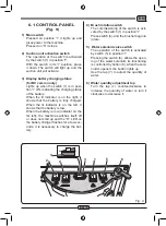
6.1 CONTROL PANEL
(Fig. 9)
1) Main switch
Pressed on position “I” it lights up and
gives power to the machine.
Pressed on “0” it stops.
2) Suction unit activation switch
The operation of the switch is activated
by the switch (1) in position “I”.
With the switch in its “I” position, press
it down. The switch will light up and the
suction unit will activate.
3) Display battery charging status
(for BC version only)
Lights up when the switch (1) is in posi-
tion “I” ON, indicating the charging status
of the battery.
When the lit indicator is on the right, it
shows that the battery is fully charged.
When the lit indicator is on the left, it
shows that the battery is low.
When the battery is low (indicator on the
far left), the machine switches itself off
or does not start up and the “R” LED on
the battery charger flashes for a few sec-
onds; it is necessary to charge the bat-
tery.
4) Brush rotation switch
The commissioning of the switch is acti-
vated by the switch (1) in position “I”.
Press switch (4), and the brusher begin to
rotate.
5) Water solenoid valve switch
The operation of the switch is activated
by switch (5) in position “I”.
Pressing the switch (6), allows the open-
ing of the water solenoid, its functioning
is controlled by button (8); when the sole-
noid is opened, the button lights up.
Use the tap (7) to adjust the quantity of
water.
6) Water quantity adjustment tap
Turn the tap (7) counter-clockwise to
increase the quantity of water or turn it
clockwise to decrease it.

