background image

17

INSTALLATION MANUAL 

AIR HEATER TYPE DXC

6.2  Minimum firing time

The heater will always fire for a minimum of 1 minute, even 
if the heat demand stops. This is to avoid a large amount of 
start and stops.

 NOTICE 

 The heater will try to ignite 2 times before it stops 

and gives an error.

6.3  Summer ventilation

The fan can be set to run in the summer. Follow the 
instructions in the user manual of the special Room 
thermostat.

6.4  Overheating protection

The air heater's heat exchanger and flue system are both 
protected from excessive temperatures.

6.4.1 

Heat exchanger

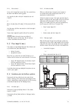
An NTC sensor is located near (or on) the heat exchanger. 
This sensor monitors the heat exchanger temperature.

If the heat exchanger becomes too hot, this sensor will 
cause the heating process to stop. Depending on the 
temperature, the air heater performs the following actions:

•  Step 1: Power reduction (when possible).
•  Step 2: Burner stop, followed by an automatic 

restart when cooled down (display: E05 / E36).

•  Step 3: Burner stop, followed by a Lock Out. A 

manual reset is required. (display L15).

 NOTICE 

 A manual reset can be done on the electronic 

circuit board or remotely with the special Room 
thermostat.

6.5  Flue passage check

The air heater is equipped with a pressure switch that 
checks the passage of combustion air through the heat 
exchanger. The pressure switch checks if there is sufficient 
movement of combustion air through the heat exchanger. 
If the pressure difference is too low, the air heater will stop. 
Error L-14 will be shown on the display.

7  Commissioning the air heater

7.1  Adjusting the settings

Prior to packaging, the safety and functioning of each 
air heater is checked in detail. It is also set to the right 
combustion efficiency.

In general, the heater does not need to be adjusted after 
installation. It is only necessary to perform a functional 
check and to obtain a flue gas analysis and record it for 
later reference.

 CAUTION! 

 Use only calibrated instruments to adjust the 

air heater.

 CAUTION! 

 Never carelessly turn the adjuster screws.

 NOTICE 

 Adjusting the control without a supporting flue 

gas analysis voids the warranty.

Only adjust the burner pressures if they differ more than 
0,5 mbar from its setting.

7.2  Commissioning the air heater

Once the unit is installed according to this manual, the unit 
can be commissioned. To do so, follow these instructions:

1.  Make sure the gas supply pipe is clean, gas tight 

and free from air.

2.  Switch on the electric supply with the maintenance 

switch.

You are now able to observe the first start-up and become 
familiar with the functioning of the heater.

 NOTICE 

 If the gas line is not purged correctly, the heater 

will attempt to start twice before going into a lock-out 
condition. In this case, manual reset is necessary.

1.  Instruct the end user of the about a safe use of the 

air heater:

a.  The presence of gas
b.  The location of the manual gas valve

Содержание DXC Series

Страница 1: ...DXC en v2 0 11 2019 INSTALLATION MANUAL AIR HEATER TYPE DXC ...

Страница 2: ...rminal 14 6 Operating the air heater 16 6 1 Manual function switch 16 6 1 Burner cycle 16 6 2 Minimum firing time 17 6 3 Summer ventilation 17 6 4 Overheating protection 17 6 5 Flue passage check 17 7 1 Adjusting the settings 17 7 2 Commissioning the air heater 17 8 Combustion settings 19 8 1 Adjusting the burner settings 19 8 2 Converting to another gas type 19 9 Troubleshooting 20 9 1 Volatile l...

Страница 3: ...manual DANGER Indicates a dangerous situation that would lead to death or severe injury WARNING Indicates a potentially dangerous situation that could lead to death severe injury or serious product damage CAUTION Indicates a potentially dangerous situation that could lead to injury or product damage NOTICE Indicates important information that is not directly related to safety 1 2 Warranty NOTICE U...

Страница 4: ...mostat 2 2 Use CAUTION Make sure the area around the air heater is dry when performing maintenance on the air heater CAUTION Always close the doors and inspection hatches of the air heater except when adjusting and checking the appliance 2 3 Maintenance Cleaning Frequent maintenance and cleaning of the air heater is necessary to ensure safe and proper operation Failure to do so could lead to damag...

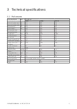
Страница 5: ... Air output max m3 h 6000 8000 10 000 Throw horizontal max m 40 45 50 Gas connection G 3 4 3 4 3 4 Electrical connection 50 Hz V 230 230 230 Electrical power consumption kW 0 8 0 9 1 4 Stand by electrical power consumption kW 0 004 0 004 0 004 Electrical current max A 3 5 3 9 6 1 Protection class IPX4D NOx emission GCV mg kWh 139 126 135 NOx class 3 3 3 Flue gas amount max kg h 122 150 199 Chimney...

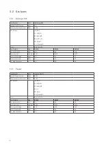
Страница 6: ... 7 8x 3 7 Burner pressure high mbar 6 5 7 4 7 7 Burner pressure low mbar 3 0 3 2 3 5 CO2 High indication 8 3 8 3 8 3 3 2 2 Propane Specification Unit Propane G31 P Nominal supply pressure mbar 30 50 Supply pressure min max mbar 25 50 Gas category II2 H3 P B P NL II2 EK3 B P DE II2 ELL3 B P BE I3 P FR II2 Er3 P PL II2 ELwLs3 B P Class B22 C12 C32 Specification Unit DXC60 DXC80 DXC100 Gas consumptio...

Страница 7: ...it DXC60 DXC80 DXC100 Gas consumption m3 h 3 9 5 0 6 5 Burner injectors n x Ømm 5x 2 3 6x 2 3 8x 2 3 Burner pressure high mbar 13 5 15 0 14 5 Burner pressure low mbar 6 0 6 0 6 5 CO2 High indication 9 2 9 2 9 2 3 3 Dimensions The dimensions of this air heater can be found in figure 1 B 1080 1125 A 2100 T1 T2 T3 T5 T4 T5 T4 T3 Figure 1 Dimensions of the DXC Dimension Unit DXC60 80 DXC100 A mm 575 6...

Страница 8: ...the air heater Keep the following requirements in mind when choosing a location to install your air heater WARNING Never install an air heater close to flammable materials Keep sufficient distance between the heater and any obstructions This is both for safety reasons and to allow access for service and maintenance figure 2 Make sure the air flow to and from the heater is free from obstacles at le...

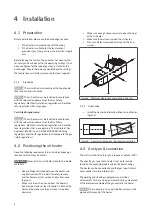
Страница 9: ...mostat The air heater can be controlled in two ways by an ON OFF signal through a bus communication system with an external interface 4 5 1 Installation requirements Following these requirements when placing the thermostat to ensure the heater functions correctly Make sure that air can circulate around the thermostat Make sure the sun does not shine directly upon the thermostat Do not place the th...

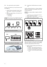
Страница 10: ...s do the following figure 8 NOTICE This functionality does not apply to an ON OFF thermostat 1 Connect the two wires of the thermostat to termi nals 4 and 5 of the first air heater 2 Connect the first air heater to the second air heater 3 Repeat for each subsequent air heater PE L 5 4 N 5 4 5 4 5 4 22 C L N PE L N L N PE L N L N PE L N L N 1 2 3 8 22 C L Neutal 4 5 L Neutal 4 5 L Neutal 4 5 1 2 3 ...

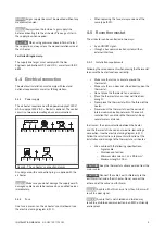
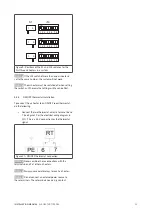
Страница 11: ...erwise the settings will have no effect 4 5 4 ON OFF thermostat installation To connect the air heater to an ON OFF room thermostat do the following Connect the two thermostat wires to terminal 6 and 7 see figure 10 or the electrical wiring diagram in 11 This is a 24 V connection for the thermostat signal Figure 10 ON OFF thermostat connection NOTICE Never combine these connections with the termin...

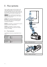
Страница 12: ...l and for the piping between the heater and the terminal This is the only way the installation will be approved NOTICE Local regulations can require the flue terminal to be placed at least 0 6 m above roof level NOTICE Local regulations can require a minimum distance between the flue terminal and air ventilation openings on the building 5 1 Flue terminals The following flue terminals are compatibl...

Страница 13: ...stem when the air heater is heating up This condensate will evaporate if the heater is operating for a longer period of time The forming of condensate depends on the following factors 5 3 1 Air heater type Condensate is especially likely to form in the smaller heaters 25 kW Condensate will most likely not form in the larger heaters 25 kW 5 3 2 Air heater location When an air heater burns frequentl...

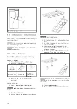
Страница 14: ...e positioned 5 4 1 2 Installation 1 Create a hole from the outside of the roof CAUTION Make sure no debris or dust gets into the air heater 2 Install the weather collar 3 Carefully insert the flue terminal from the outside CAUTION Do not rotate the cap 4 Put the flue terminal into a vertical position Use a level 5 OPTIONAL If desired fit cover plates These are supplied separately 6 Place the suppl...

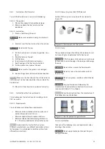
Страница 15: ...een the flue system and combustible materials of 40 mm Minimum depth of female sockets of 40 mm Minimum slope of horizontal piping of 50 mm m 3 This allows condensate to flow to the heater NOTICE Use brackets that match the flue system Different manufacturers use different connection systems for flue pipes It is not allowed to combine systems from different manufacturers 5 4 3 2 Elements system AL...

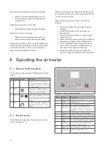
Страница 16: ...omply with national and local regulations 6 Operating the air heater 6 1 Manual function switch The air heater can be manually controlled with a function switch No Function Symbol Description 0 Off The heater is off The power to the electrical components is interrupted neutral and live The earth connection is not interrupted 1 Auto The heater is in standby mode and ready to use It will start to bu...

Страница 17: ...f there is sufficient movement of combustion air through the heat exchanger If the pressure difference is too low the air heater will stop Error L 14 will be shown on the display 7 Commissioning the air heater 7 1 Adjusting the settings Prior to packaging the safety and functioning of each air heater is checked in detail It is also set to the right combustion efficiency In general the heater does ...

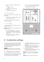
Страница 18: ...e will automatically end after 10 minutes Figure 18 Using the display 8 Combustion settings In principle it is not necessary to adjust the control shortly after commissioning the air heater When the control does have to be adjusted after a period of use or after installing a new heater this must be done by a qualified person using calibrated equipment DANGER A poor adjustment can lead to overheati...

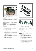
Страница 19: ...nd ionisation cables from the burner unit 4 Disconnect the burner manifold from the gas valve This is a clamp coupling 5 Unscrew the screws that attach the burner mani fold to both ends of the endplates of the burner unit 6 Remove the burner manifold 7 Remove the gas injectors from the burner tube 8 Select the correct injectors see 3 2 NOTICE The injectors have a stamp that corresponds to the diam...

Страница 20: ...re 4 L 33 to 38 Internal error Internal error 13 L 43 Overheating Heat exchange sensor is overheated too often 3 9 2 Temporary errors The table below describes the temporary errors that can occur These will disappear automatically after the cause has been resolved Display Error type Description Case E 00 to 04 Internal error Internal error 13 E 05 Overheating Heat exchange sensor is overheated 3 E...

Страница 21: ...ffer too much replace the sensor Case 5 Too many flame failures while burning The gas supply is not constant This results in a drop in gas supply pressure while burning and causes the flame to extinguish Check the gas supply pressure while the heater is burning The burner pressure for Low fire is too low This causes the flame to extinguish because it is too small to be detected Check the burner pr...

Страница 22: ... already installed do the following 1 Set the thermostat to the lowest setting 2 Close the manual gas valve 3 Turn off the power supply to the air heater using the maintenance switch CAUTION Always check for gas leaks after working on the air heater CAUTION Do not use water when cleaning the air heater CAUTION The heater must be electrically isolated during servicing Water can be used to clean the...

Страница 23: ...Clean the inside of the flue fan 9 Check the air supply and the flue discharge for dirt and clean it 10 Reassemble the burner unit If necessary Use new gaskets 10 4 Extensive maintenance in poultry sheds WARNING Air heaters that are used in poultry sheds must be cleaned and inspected after every clean out before disinfection and the spreading of sawdust on the floor CAUTION The heat exchanger can ...

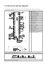
Страница 24: ... heat exchanger V2 High low valve with rectifier Figure 20 Electrical wiring diagram DXC60 100 L N 230 Vac PE N L L N PE 11 12 13 14 PE N L M1 4 5 6 7 PE RT Bus com Figure 21 Main connections for installation 20K 25 C F1 5AT 20K 25 C J9 1 J9 3 J9 2 J9 4 J6 1 J6 8 J6 2 J6 9 J6 3 J6 10 J6 4 J6 11 J6 5 J6 12 J6 6 J6 13 J7 1 J7 2 J7 3 J7 4 J7 5 J7 6 J7 7 J7 8 J7 9 J7 10 J12 1 J12 4 J12 2 J12 5 J12 3 J...

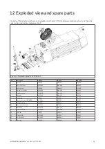
Страница 25: ...rode GA3400 GA3400 GA3400 3 Ignition cable IB3929 IB3929 IB3929 4 Ionisation electrode GA3402 GA3402 GA3402 5 Combustion fan GA4516 GA4516 GA4517 6 Gas valve GA3314 GA3314 GA3314 7 System fan IP4811 IP4801 IP4813 8 Burner control unit EBM966 GY5901 GY5901 GY5901 9 Pressure switch IB3904 IB3911 IB3904 10 Heat exchange sensor GY3935 GY3935 GY3935 11 Gasket set GA6716 GA6716 GA6716 13 Selection switc...

Страница 26: ...ng to appliances burning gaseous fuels 2014 35 EU LVD relating to the electric safety of appliances 2014 30 EU EMC relating to electromagnetic compatibility of appliances 2006 42 EG MD relating to the safety of machinery Goods should be installed and used in accordance with our instructions and with the applicable local and international rules Installation should be done by an authorized qualified...

Страница 27: ...27 INSTALLATION MANUAL AIR HEATER TYPE DXC ...

Страница 28: ......

Отзывы: