16
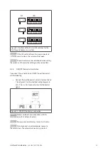
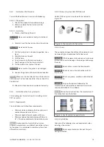
Requirements for horizontal and non-vertical piping:
• Maximum distance between brackets of 1 m.
• On tensile joints; maximum distance between
brackets of 2 m.
Follow the manufacturer’s instructions.
• Spread the brackets evenly along the piping.
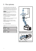
Requirements for vertical piping:
• Maximum distance between brackets of 2 m.
• Spread the brackets evenly along the piping.
Always place a bracket on or near a bend or elbow piece,
except if the flue pipes before and after the elbow piece
are shorter than 0,25 m. In this case, fix the second
element after the elbow with a bracket.
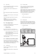
Every flue discharge system needs to be secured with at
least one bracket. The first bracket needs to be within the
first 0,5 m of the air heater.
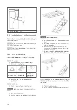
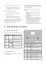
When installing a flue system inside a shaft, do the
following:
1. Check the components for possible damage or
blockage.
2. Check that the pipe is at the right slope (see
Requirements).
3. Mark the flue pipes and fresh air pipes to avoid
mixing them up.
4. Make sure that the pipes extend for at least 50 mm
when passing through a wall or other obstacle.
5. Fix the last element before entering the shaft in
place. If the last element is an elbow piece, the
next element must also be fixed in place.
6. Check if ventilation openings and inspection
hatches comply with national and local regulations.
6 Operating the air heater
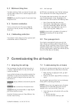
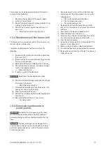
6.1 Manual function switch
The air heater can be manually controlled with a function
switch.
No.
Function
Symbol
Description
0
Off
The heater is off. The power to the
electrical components is interrupted
(neutral and live). The earth connection
is not interrupted.
1
Auto
The heater is in standby mode and
ready to use. It will start to burn when a
thermostat connection is made.
2
Auto + fan
+
The heater is in standby mode and the
fan is running continuously. The heater
will burn when a thermostat connection
is made.
3
Burn
The heater is burning continuously,
independent from any other control
settings.
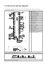
6.1 Burner cycle
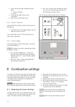
The air heater’s display shows the current status of the
burner cycle (figure 17).
Figure 17 - Display of the air heater
Display
Status
Description
0
Stand-by
Waiting for heat demand.
1
Reset
Software reset.
3
Pre-check
Zero position check pressure switch.
4
Pre-purge
30 seconds of pre ventilation by the
combustion fan. The pressure switch is
checked.
5
Pre-ignition
Ignition without opening the gas valve.
6
Ignition
5 seconds of ignition. The gas valve opens.
7
Flame check The air heater checks if the flame is present.
8
Burn
The heater fires up and starts to modulate.
9
Minimum
Before the flame stops, the burner will
modulate to minimum power.
10
Burner off
The gas valve closes. The flame stops.
11
Post purge
Burner fan purges with fresh air.
System fan cools the heat exchanger.
Содержание DXC Series
Страница 1: ...DXC en v2 0 11 2019 INSTALLATION MANUAL AIR HEATER TYPE DXC ...
Страница 27: ...27 INSTALLATION MANUAL AIR HEATER TYPE DXC ...
Страница 28: ......

