background image

4

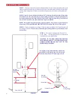
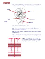
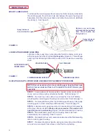
STEP 6. Attach cable clamp to the coax cable 16" from the cable clamp
on the gear housing.

STEP 7. Attach cable clamp to roof 

3" in front of baseplate as shown in

Figure 3, use 7/16" flat washer between screw head and clamp, apply
sealing compound over mounting screw head.

STEP 8. Feed downlead throught the roof using a Model CE-1000 cover
plate (included with hardware), Figure 3A. Weatherproof cable entry by
applying sealant under lip of roof-thru plate and where cable enters roof.
Attach plate to roof with screws provided.  Apply sealant over screws and
around edge of roof-thru plate, making sure cable entry is sealed.  Secure
cables as necessary to prevent whipping.  

DO NOT MAKE CONNECTION

ON TOP OF ROOF unless there is no other option, it is very difficult to
weatherproof outside connection.  If downlead connection is made on
top of roof make sure to weatherproof connection!

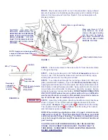
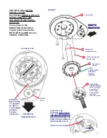
STEP 9. Assemble ceiling plate, directional handle and crank handle as
shown in Figure 5. The circled numbers indicate placement from the
ceiling down.  Example:  The ceiling plate  1  is located next to the ceiling.
The elevation crank handle  8   is farthest from the ceiling. The number
also indicates sequence of assembly.

NOTE: When installing polyethylene shim, # 3, page 5, slide shim onto
shaft as far as it will go.  Then slide directional handle up over shaft
and shim and onto the  gear housing.  Two shims are supplied in case
one is not enough to create a snug fit between directional handle and
gear housing.

CAUTION: USE CAUTION WHEN INSTALLING THE ELEVATING
CRANK.  ONCE SCREW TOUCHES SHAFT, TIGHTEN ONLY 1/4
TURN MORE.   SCREW SIMPLY HOLDS ELEVATING CRANK ON.
DO NOT OVERTIGHTEN!

STEP 5. Mount antenna and lift on roof in travel position. Apply a liberal
amount of approved nonhardening sealing compound on bottom of base
plate and roof area around hole. See Figure 3. Secure base plate with
screws provided.

Cable clamp on gear housing.

CAUTION:  DO NOT GET
SEALING COMPOUND ON
BEARING SURFACE BETWEEN
BASE PLATE AND ROTATING
GEAR HOUSING.  DO NOT
PAINT TOP OF BASE PLATE OR
AROUND ROTATING GEAR
HOUSING.

3" min.

FIGURE 3

Attach cable clamp here.

Make sure there is 16" of
coax between the cable
clamp on the gear housing
and the one 3" in front of
base plate. TOO MUCH OR
TOO LITTLE WILL CAUSE
DAMAGE TO COAX.

Downlead
from antenna

#10 x 1" Screws

NOTE:  Apply non-hardening sealing
compound between Base Plate and
roof of vehicle.

CE-1000

Downlead
connects to
satellite
receiver

FS-8100 male-to-male
F-connector
(if required)

FIGURE 3A

INSIDE RV

Содержание RD-4600

Страница 1: ...710 and 5 554 998 Made in U S A Winegard Company 3000 Kirkwood St Burlington IA 52601 2000 319 754 0600 FAX 319 754 0787 Printed in U S A Winegard Company 2001 2451099 Rev 6 05 01 OWNER S MANUAL INSTALLATION INSTRUCTIONS IMPORTANT INSTALL POINT OF BASE TOWARD FRONT OF VEHICLE ...

Страница 2: ... must be level for proper operation If you have a curved roof you should use a Winegard Models RW 1000 IW 1001 wedge kits to level the system STEP 2 Position template on roof pg 15 this manual and drill a 1 3 4 hole through roof and ceiling of vehicle Take care to avoid damage to wiring which may run between roof and ceiling STEP 3 The mount is designed to fit roofs 1 to 6 3 4 thick Cut elevating ...

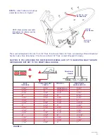
Страница 3: ...3 1 Directional Handle FIGURE 2 NOTE Make sure that coax cable fits between the reflector and the fixed feed arm 4 5 16 18 Hex Nut 4 5 16 Flat Washer 4 5 16 18 x 5 8 Flat Head Bolt Rev 6 05 01 STEP 4 Attach reflector to backup assembly as shown in Figure 2 The mount is designed to fit roofs 1 to 4 3 4 thick If roof is less than 4 3 4 thick cut elevating shft and directional handle to size See tabl...

Страница 4: ...he number also indicates sequence of assembly NOTE When installing polyethylene shim 3 page 5 slide shim onto shaft as far as it will go Then slide directional handle up over shaft and shim and onto the gear housing Two shims are supplied in case one is not enough to create a snug fit between directional handle and gear housing CAUTION USE CAUTION WHEN INSTALLING THE ELEVATING CRANK ONCE SCREW TOU...

Страница 5: ...tional Handle ALIGN POINTER WITH ANTENNA TRAVEL POSITION 2 4 10 Phillips Flat Head Screws FIGURE 8 5 ELEVATING CRANK HANDLE When installed extends 2 1 4 from ceiling Snap Handle into base when not in use CAUTION After INITIAL INSTALLATION the antenna SHOULD ROTATE APPROXIMATELY 360 DEGREES FROM TRAVEL POSITION The pointer on the DIRECTIONAL HANDLE should point towards the ROTATION CLAMP when in TR...

Страница 6: ...nting at 145 on the directional dial STEP 7 Refer to table below and turn elevation crank counter clockwise CCW the number of turns indicated to get the elevation shown by the receiver One full turn equals approximately 7 of elevation change OPERATION STEP 1 Using a compass determine which direction is North It is recommended that you step outside to perform this step Standing in or near coach RV ...

Страница 7: ...ance is met The number of turns will vary according to the elevation angle the antenna was set to STEP 4 Move rotation clamp to the LOCK position Antenna is now locked in travel position STEP 5 Snap elevation crank into place CAUTION UNDER NO CONDITIONS LOWER ANTENNA IN ANY POSITION EXCEPT TRAVEL POSITION DO S 1 Do check parking location for obstructions before raising antenna 2 Do carefully raise...

Страница 8: ...k spring directional handle Parts list page 12 STEP 2 Remove hex nuts cable clip and washer from bolt holding elevating tube in rotating gear housing and remove bolt Parts list page 10 STEP 3 Removeplasticplugfromtopofrotatinggearhousing disengage elevating gear remove elevating shaft assembly Parts list page 10 STEP 4 Lubricate worm gear assembly on new elevating shaft assembly with spray silicon...

Страница 9: ...r may not receive any signal 9 Contact Dealer or Winegard Service Department ANTENNA DOES NOT OR IS HARD TO ROTATE 1 Inspect antenna on roof Make sure that mount has not been damaged 2 Check for caulking between gear housing and baseplate 3 Lubricate mount per procedure on page 8 4 Contact Dealer or Winegard Service Department ANTENNA DOES NOT OR IS HARD TO RAISE 1 Inspect antenna on roof Make sur...

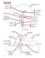
Страница 10: ... procedure on page 8 RD 4610 Only Aluminum Baseplate P N 3100524 4 5 16 Hex Nut P N 2160230 4 5 16 Flat Washer P N 2160027 1 4 20 X 2 5 Hex Bolt P N 2160237 2 1 4 Flat Washer P N 2160024 REAR VIEW Model RP 3000 Elevating Gear Elevating Tube P N 3506038 2 1 4 Flat Washer P N 2160039 4 1 4 20 Hex Nut Nylock P N 2160220 Digital Elevation Device If attached the 1 4 20 x 1 75 Hex Bolts are replaced wit...

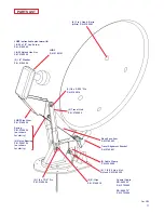
Страница 11: ...shown for clarity 4 Nylon Bearing P N 2200726 not shown for clarity Fixed Feed Arm P N 2745063 Travel Alignment Bracket P N 2745061 Coaxial Cable RD 4600 20 P N 2753025 RD 4646 76 P N 2753064 LNBF P N 2780161 LNBFisattachedtopivotarmwith 1 4 20 x 1 2 Cap Screw P N 2160240 1 4 20 Nylock Hex Nut P N 2160220 2 1 4 Washer P N 2160024 2 1 4 x 1 7 8 Pin P N 2160694 4 Flat Head Bolts white P N 2160361 Re...

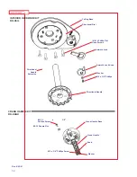
Страница 12: ...irectional Handle Azimuth Lock Azimuth Lock Knob Washer 10 x 3 8 Phillips 8 32 Square Nut Crank Handle Base Crank Handle Knob Washer 8 32 x 3 8 Phillips Screw 10 x 3 8 Phillips Screw Directional Handle Extension PARTS LIST INTERIOR HARDWARE KIT RK CEIL CRANK HANDLE KIT RK HAND ...

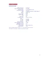
Страница 13: ...20 9 Antenna width 19 5 F D 0 59 Offset angle 24o Frequency range 10 95 12 75 GHz Gain 11 2 GHz 33 22 dBi 12 1 GHz 33 89 dBi 12 6 GHz 34 23 dBi Aperture efficiency 73 Cross polarization on axis 21 dB Beamwidth at 3 dB 3 5o Beamwidth at 10 dB 7 0o Wind loading Up to hurricane force Shipping weight 16 lbs DSS is a registered trademark of DIRECTV Inc a unit of Hughes Electronics Corporation DISH Netw...

Страница 14: ...htning ice or corrosive environments such as salt spray and acid rain The Two Year Warranty is provided on the condition that the equipment is properly delivered with all handling and freight charges prepaid to your Winegard dealer for repair or return to our factory at the above address Winegard dealers will arrange for the replacement or repair and return to you without charge the product which ...

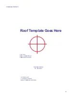
Страница 15: ...15 Roof Template Goes Here 1 3 4 DIA DRILL COMPLETELY THROUGH CEILING TOWARD FRONT OF VEHICLE 1 8 DRILL BIT 10 HOLES DO NOT DRILL THROUGH CEILING RD 4600 4646 TEMPLATE ...

Страница 16: ...16 Printed in U S A Winegard Company 3000 Kirkwood Street Burlington Iowa 52601 2000 Winegard Company 1999 2451099 Rev 5 99 ...

Отзывы: