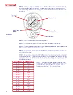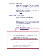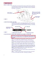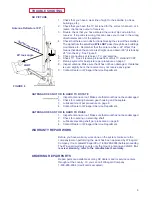
2
Cen
te
r R
oof Line
FIGURE 1
INSTALLATION & ASSEMBLY
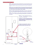
STEP 1. Choose a location for antenna that will allow it to rest in travel position with top of
reflector pointing toward rear of vehicle and to raise and rotate without interfering with other
roof-mounted equipment. Make sure inside ceiling area is clear where ceiling plate will
mount.
NOTE: Figure 1 shows minimum distance (10") antenna should be located from edge
of vehicle roof. We recommend you check with your dealer or the manufacturer to
see what provisions have been made in the roof for antenna mounting. A reinforced
area of roof as well as pre-wire downlead may be available.
NOTE:
The system must be level for proper operation. If you have a curved roof you
should use a Winegard Models RW-1000 IW-1001 wedge kits to level the system.
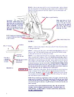
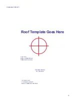
STEP 2. Position template on roof (pg. 15 this manual) and drill a 1-3/4"hole through roof
and ceiling of vehicle. Take care to avoid damage to wiring which may run between roof
and ceiling.
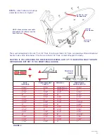
STEP 3. The mount is designed to fit roofs 1" to
6 3/4" thick. Cut elevating shaft and directional
handle to size, see table below.
CAUTION: IF YOU ARE USING THE RW-1000
ROOF WEDGE, ADD 1/2" TO ELEVATING SHAFT
LENGTH GIVEN BELOW, BUT NOT TO THE
DIRECTIONAL HANDLE.
Front of the RV
26"
34" DIA.
OPERATING
AREA
NOT TO SCALE
17" RADIUS
It is highly recomended that the antenna be
mounted on roof center line. Do not mount
antenna closer than 10" from edge of roof.
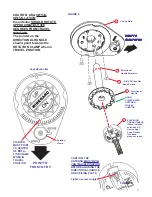
Vehicle Roof
RW-1000
Roof Wedge
IW-1001
Ceiling Wedge
Antenna Controls
19.50"


