Installation and operating instructions WILO Mather and Platt
–
Sump Pumps 27
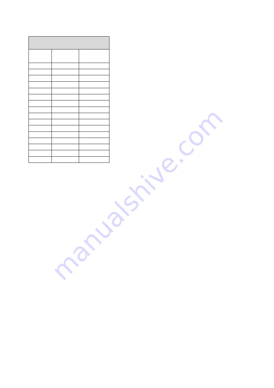
Recommended Tightening Torques for
fasteners (Nm)
Thread
Size
Material
Class 8.8
Material
Class 10.9
M4
3
4.3
M5
6
8.9
M6
10.3
15.1
M8
25
37
M10
50
74
M12
67
128
M14
139
205
M16
214
316
M20
431
615
M22
586
835
M24
745
1060
M27
1090
1560
M30
1480
2105
M33
2013
2865
M36
2586
3680
M39
3348
4760
10.2 Overhaul maintenance
•
After a long period of service, wear will occur in parts of the
pump, necessitating the renewal of a few components. Logbook
records will indicate wear as gradual deterioration of
performance is noticed. Once this is known, pumps should be
taken for overhaul. It is recommended that yearly stripping &
checking of wear & tear and clearances should be done and
overhauling where required.
•
If related pair of components show a marked degree of wear in
relation to the rest of the unit, then it may be sufficient to renew
only the heavily worn components. If the wear is uniform
throughout the pump, then all wearable components may
require renewal.
•
Measurements should be taken and recorded of all wearable
components at the first, and every subsequent overhaul period.
Reference to these records will enable an accurate assessment
of the rate of wear to be made, and a reasonably accurate
forecast regarding when a particular component may require
renewal can be made.
•
Information regarding original design dimensions and clearances
is furnished in data sheet. Any other information, if needed, can
be requested from Service Department, WILO Mather Platt. Such
requests must quote name plate number and type of the pump
in question.
The parts most likely to be affected are:
•
Impeller
•
Neck Rings
•
Sleeves
•
Stuffing Box Bush
•
Bearings
•
Coupling Bushes
Before commencing dismantling operations, ensure that the
following tools and tackles are available:
•
A crane / chain pulley block suitable for handling the weight
of pumping unit.
•
A selection of ring and open-ended spanners in Metric sizes.
•
Eyebolts in Metric sizes.
•
Cotton rope, wire rope and slings.
•
Hardwood and metal packing blocks.
•
Miscellaneous tools including a set of Allen keys, screw
drivers, files etc.
•
Extractor / puller for bearing and coupling.
•
The torque value to be set for a particular size of screw is
dependent upon:
•
Material of screw
•
Parent metal
•
Whether the screw is untreated or plated
•
Whether the screw is dry or lubricated
•
The depth of the thread
10.3 Disassembling the Pump
10.3.1 Disassembling the top Motor
•
Isolate the pump motor electrically
•
Isolate the pump system hydraulically
•
Clear the area of any equipment that might impede the free
lifting of the pump
•
Disconnect and remove the driving coupling
•
Disconnect the electrical supply cables from the motor
terminal block
•
Attach slings and lifting apparatus to the motor lifting
attachments
•
Remove the screws / bolts, or nuts, from the motor flange
and lift the motor off from the motor stool.
•
Support the motor on timber packing blocks with the
coupling hub clear off the ground
10.3.2 Removing pump from pit
•
Dismantle the discharge pipeline, delivery valves and non-
return valve from the delivery pipe.
•
Then remove the complete pump assembly along with
mounting plate away from the sump.
10.3.3 Disassembling of pump parts
•
Remove the coupling key & take off the coupling half from
top pump shaft.
•
Remove Adjusting ring from the shaft.
•
Dismantle the delivery pipe (TOP) from the casing.
•
Remove bearing cover, unscrew lock washer and remove
bearing cartridge along with bearing from top shaft.
•
Unscrew the fasteners and remove the motor stool
•
Remove casing from the bottom support pipe along with the
strainer.
•
No need to remove the strainer from casing unless it is to be
cleaned or replaced.
•
Remove the locking screw and unscrew the impeller nut
•
Remove the impeller
•
Unscrew the fasteners and remove the back cover along
with the bush bearing
•
Remove shaft sleeve from the shaft.
•
Remove intermediate assembly consists of the support
pipes and intermediate shafts and bearing brackets.
•
Remove muff coupling assembly
•
Remove the intermediate bracket/support pipe assembly
fasteners and remove top support pipe.
Содержание 4/5 TYPE 17
Страница 24: ...Installation and operating instructions WILO Mather and Platt Sump Pumps 24 ...
Страница 39: ...Installation and operating instructions WILO Mather and Platt Sump Pumps 39 NOTES ...
Страница 40: ...Installation and operating instructions WILO Mather and Platt Sump Pumps 40 NOTES ...
Страница 41: ...Installation and operating instructions WILO Mather and Platt Sump Pumps 41 NOTES ...


