


WILDEN PUMP & ENGINEERING, LLC
22
WIL-11111-E-03
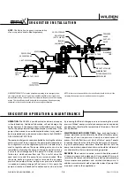
R E A S S E M B L Y H I N T S & T I P S
ASSEMBLY:
Upon performing applicable maintenance to the air distribution
system, the pump can now be reassembled. Please refer to the
disassembly instructions for photos and parts placement. To reas-
semble the pump, follow the disassembly instructions in reverse
order. The air distribution system needs to be assembled first,
then the diaphragms and finally the wetted path. Please find the
applicable torque specifications on this page. The following tips
will assist in the assembly process.
• Lubricate air valve bore, center section shaft and pilot spool
bore with NLGI grade 2 white EP bearing grease or equivalent.
• Clean the inside of the center section shaft bore to ensure no
damage is done to new seals.
• A small amount of NLGI grade 2 white EP bearing grease can be
applied to the muffl
er and air valve gaskets to locate gaskets
during assembly.
• Make sure that the exhaust port on the muffl
er plate is cen-
tered between the two exhaust ports on the center section.
• Stainless-steel bolts should be lubricated to reduce the possi-
bility of seizing during tightening.
SHAFT SEAL INSTALLATION:
PRE-INSTALLATION
• Once all of the old seals have been removed, the inside of the
bushing should be cleaned to ensure no debris is left that may
cause premature damage to the new seals.
INSTALLATION
The following tools can be used to aid in the installation of the
new seals:
Needle Nose Pliers • Phillips Screwdriver • Electrical Tape
• Wrap electrical tape around each leg of the needle nose pliers
(heat shrink tubing may also be used). This is done to prevent
damaging the inside surface of the new seal.
• With a new seal in hand, place the two legs of the needle nose
pliers inside the seal ring. (See Figure A.)
• Open the pliers as wide as the seal diameter will allow, then
with two fi ngers pull down on the top portion of the seal to
form kidney bean shape. (See Figure B.)
• Lightly clamp the pliers together to hold the seal into the kid-
ney shape. Be sure to pull the seal into as tight of a kidney shape
as possible, this will allow the seal to travel down the bushing
bore easier.
• With the seal clamped in the pliers, insert the seal into the bush-
ing bore and position the bottom of the seal into the correct
groove. Once the bottom of the seal is seated in the groove,
release the clamp pressure on the pliers. This will allow the seal
to partially snap back to its original shape.
• After the pliers are removed, you will notice a slight bump in
the seal shape. Before the seal can be properly resized, the
bump in the seal should be removed as much as possible. This
can be done with either the Phillips screwdriver or your fi nger.
With either the side of the screwdriver or your fi nger, apply
light pressure to the peak of the bump. This pressure will cause
the bump to be almost completely eliminated.
• Lubricate the edge of the shaft with NLGI grade 2 white EP
bearing grease.
• Slowly insert the center shaft with a rotating motion. This will
complete the resizing of the seal.
• Perform these steps for the remaining seal.
Figure A
SHAFT SEAL
TAPE
Figure B
SHAFT SEAL
TAPE
NEEDLE NOSE PLIERS
PRO-FLO X™ MAXIMUM TORQUE SPECIFICATIONS
Description of Part
Torque
Air Valve
13.6 N•m (120 in-lbs)
Air Chamber/Center Block
27.1 N•m (20 ft-lbs)
Outer Pistons, Rubber & PTFE
105.8 N•m (78 ft-lbs)
Liquid Chamber to Air Chamber, Aluminum
47.5 N•m (35 ft-lbs)
Liquid Chamber to Air Chamber, Stainless Steel
17.6 N•m (13 ft-lbs)
Manifolds, T-section, Aluminum
27.1 N•m (20 ft-lbs)
Manifolds, Stainless Steel
33.9 N•m (25 ft-lbs)
Содержание HX400S
Страница 25: ...N O T E S ...
Страница 30: ...N O T E S ...


