6
.
5
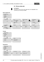
M
enu schematic
I
nformation
:
D
epending on the version and application
,
the highlighted menu
windows are not always available
.
B
asic adjustment
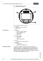
1
▶
B
asic adjustment
D
isplay
D
iagnostics
S
ervice
I
nfo
1
.
1
S
ensor address
126
1
.
1
U
nit
U
nit of measurement
bar
▼
T
emperature unit
°
C
▼
1
.
2
P
osition correction
O
ff
set
P
=
0
.
2
mbar
0000
mbar
1
.
3
M
in
.
adjustment
000
.
0
%
=
0
.
0
mbar
0
.
0
mbar
1
.
4
M
ax
.
adjustment
100
.
00
%
=
100
.
00
mbar
0
.
0
mbar
1
.
5
D
amping
0
s
1
.
6
L
inearisation curve
linear
▼
1
.
7
S
ensor
-
TAG
S
ensor
D
isplay
2
B
asic adjustment
▶
D
isplay
D
iagnostics
S
ervice
I
nfo
2
.
1
D
isplayed value
PA
-
O
ut
2
.
4
L
ighting
S
witched o
ff
▼
D
iagnostics
3
B
asic adjustment
D
isplay
▶
D
iagnostics
S
ervice
I
nfo
3
.
1
P
ointer
p
-
min
.: -
5
.
8
mbar
p
-
max
.:
167
.
5
mbar
T
-
min
.: -
12
.
5
°
C
T
-
max
.:
+
85
.
5
°
C
3
.
2
S
ensor status
OK
3
.
3
.
1
T
rend curve
S
tart trend curve
?
32
P
rocess pressure transmitter
IPT
-
11
V
ers
.
4
.
0
-
ceramic sensor
•
P
ro
fi
bus
PA
6
S
et up with the indicating and adjustment module
31547
-
EN
-
081211

