E
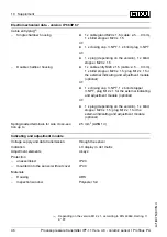
lectromechanical data
-
version
IP
66
/
IP
67
C
able entry
/
plug
15
)
-
S
ingle chamber housing
l
1
x cable gland
M
20
x
1
.
5
(
cable
:
ø
5
…
9
mm
),
1
x blind stopper
M
20
x
1
.
5
or
:
l
1
x closing cap
½
NPT
,
1
x blind plug
½
NPT
or
:
l
1
x plug
(
depending on the version
),
1
x blind
stopper
M
20
x
1
.
5
-
D
ouble chamber housing
l
1
x cable entry
M
20
x
1
.
5
(
cable
:
ø
5
…
9
mm
),
1
x blind stopper
M
20
x
1
.
5
;
plug
M
12
x
1
for
the external indicating and adjustment module
(
optional
)
or
:
l
1
x closing cap
½
NPT
,
1
x blind stopper
½
NPT
,
plug
M
12
x
1
for the external indicating
and adjustment module
(
optional
)
or
:
l
1
x plug
(
depending on the version
),
1
x blind
stopper
M
20
x
1
.
5
;
plug
M
12
x
1
for the
external indicating and adjustment module
(
optional
)
S
pring
-
loaded terminals for wire cross
-
sec
-
tion up to
2
.
5
mm
²
(
AWG
14
)
I
ndicating and adjustment module
V
oltage supply and data transmission
through the sensor
I
ndication
LC
display in dot matrix
A
djustment elements
4
keys
P
rotection
-
unassembled
IP
20
-
mounted into the sensor without cover
IP
40
M
aterials
-
H
ousing
ABS
-
I
nspection window
P
olyester foil
15
)
D
epending on the version
M
12
x
1
,
according to
DIN
43650
,
H
arting
,
7
/
8
"
FF
.
46
P
rocess pressure transmitter
IPT
-
11
V
ers
.
4
.
0
-
ceramic sensor
•
P
ro
fi
bus
PA
10
S
upplement
31547
-
EN
-
081211

